36
MOTORIDUTTORE
COMANDO APERTURA ARIA
(14/2 - 20/2)
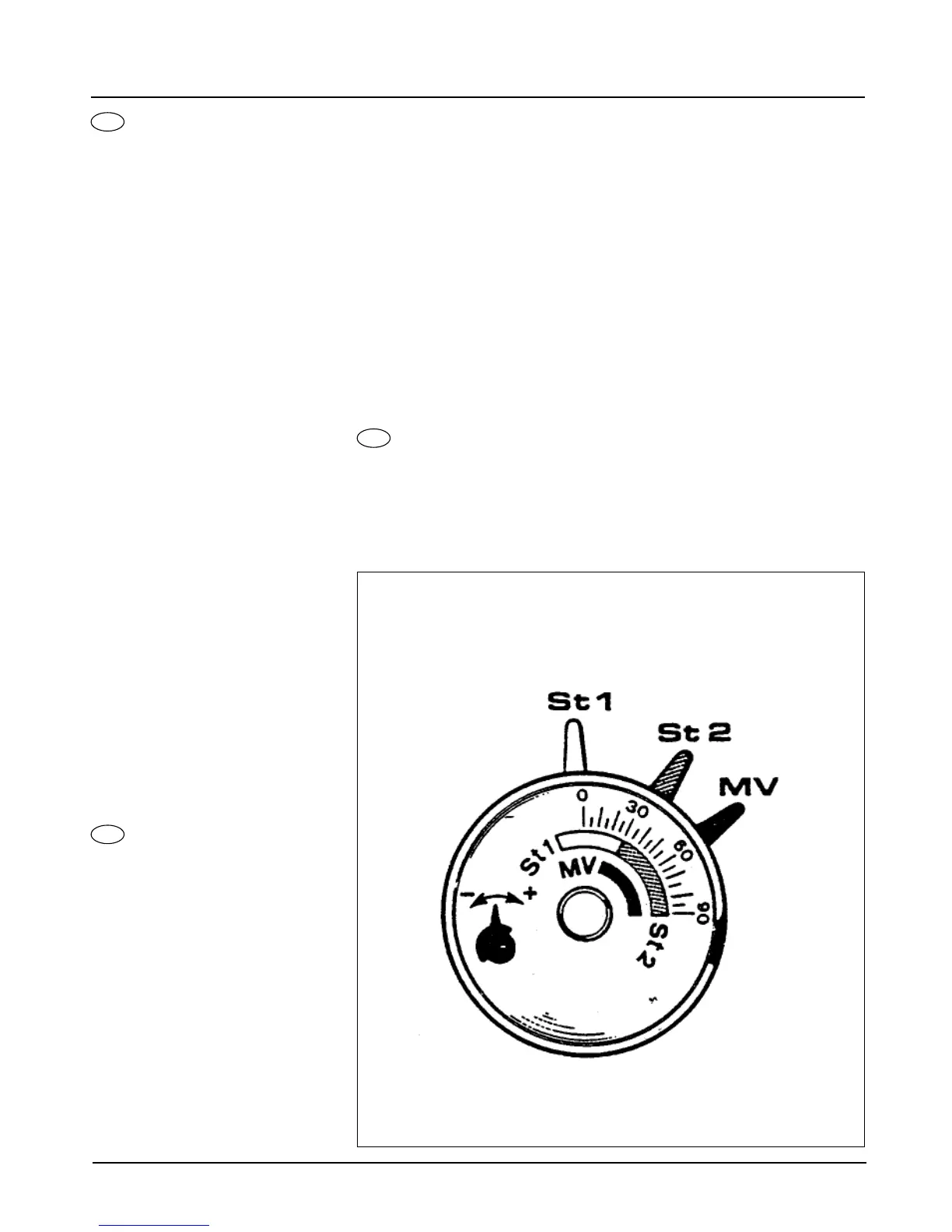
Nel motoriduttore l’azionamento dei contatti
ausiliari e di fine corso è ottenuto con camme
facilmente accessibili e regolabili la cui taratura
è facilitata da una scala graduata.
Taratura del punto di scatto dei contotti.
Awertenze generali
CAMMA ST2 (rossa) - Camma per la posizione
di apertura massima della serranda (potenza
massima con entrambi gli stadi in funzione).
CAMMA ST1 (blu) - Camma per la posizione
di apentura minima della serranda (potenza
minima con il solo 1° stadio in funzione).
CAMMA MV (nera) - Camma ausiliaria per il
consenso all’apertura della valvola del 2° sta-
dio.
Awertenze pratiche per la regolazione del
motoriduttore.
Il motoriduttore è tarata in sede di collaudo con
le seguenti posizioni:
CAMMA ST2: posizionata a 60° circa.
CAMMA ST1: poszionata in modo che la ser-
randa si trovi a 15° ÷ 30°.
CAMMA MV: posizionata in modo che l’elet-
trovalvola del 2° stadio si apra quando la ser-
randa si trova a 30° ÷ 45°.
Modifiche a questa taratura in sede di installa-
zione sono eseguibili anche a bruciatore in fun-
zione agendo nel modo seguente:
CAMMA ST2: per aumentare l’apertura dclla
serranda presa aria ruotare la camma in senso
orario (+), viceversa ruotare in senso antiorario
(-) per diminuire l’apertura.
CAMMA ST1: per aumentare l’apertura della
serranda presa aria ruotare la camma in senso
orario (+), viceversa ruotarla in senso antiorario
(-) per diminuire la portata d’aria.
CAMMA MV: per ritardare l’apertura dell’elet-
trovalvola del 2° stadio, ruotare la camma in
sensa orario (+); viceversa ruotarla in senso
antiorario (-) per anticiparne l’apertura.
GEARED MOTOR
CONTROLLING AIR DELIVERY
(14/2 - 20/29)
The geared motor limit switch and auxiliary con-
tacts are triggered by easily accessible adjusta-
ble cams, which can be set against o gradua-
ted scale.
Setting the contact triggering point
General information
CAM ST2 (red) - Cam controlling air valve fully-
open position (maz. firing rate with both stages
in operation).
CAM ST1 (blue) - Cam controlling minimum air
flow condition (min. firing rate, Ist stage only in
aperation);
CAM MV (black) - Auxiliari cam activating the
2nd stage valve.
Recommendations to properly set the geared
motor.
The geared motor is set upon testing as follows.
CAM ST2: is set ot approx. 60°.
CAM ST1: is set in such o way that the air shut-
off valve is set at 15° to 30°.
CAM MV: is set in such a way that the 2nd-
stage valve opens when the air shut-off valve is
at 30° to 45°.
The above settings can be abjusted when instal-
ling the unit also while the burner is in operation
as follows:
CAM ST2: Rotate the cam clackwise to open
the air intake valve (+); Rotate the cam counter-
clockwise (-) to close the air intake valve.
CAM ST1: Rotate the com clockwise (+) to
open the air intake valve Rotate the carn coun-
terclock wise (-) to close air flow rate.
CAM MV: Rotate the cam clockwise (+) to
delay opening of the 2nd stage solenoid valve
Rotate the cam counterclockwise (-) to advance
valve opening.
LUFTSERVOMOTOR
(TYP 14/2 UND 20/2)
Die Betatigung der Hilfs- und Endanschlagskon-
takte des Luftservomotors erfolgt durch Daumen,
die leicht zuganglich und leicht verstelbar sind.
Die richtige Verstellung wird von der
Markierungsskala erleichtert.
Verstellung der Auslösungspunkte der Kontakte.
DAUMEN ST2: für max. Öffnung der
LuFtabschußklappe (Max. Leistung bei zweistufi-
gem Betrieb).
DAUMEN ST1: für min Öffnung der
Luftabschlußklappe (Max. Leistung bei zweistufi-
gem Betrieb).
DAUMEN ST1: für min. Öffnung der
Luftabschlußklappe (Min. Leistung bei einstufi-
gem Betrieb).
DAUMEN MV: Hilfsdaumen zur Öffnung des
2. Stufen Ventils.
Anleitung zur Verstellung des Servomotors.
Der Servomotor ist beim Erproben in unserem
Werk auf folgende Positionen eingestellt.
DAUMEN ST2: etwa 60°.
DAUMEN ST1: engestellt damit die
Luftabschlußkappe bei etwa l5° ÷ 30° ist.
DAUMEN MV: eingestellt damit das 2. Stufen
Magnetventil öffnet, wenn die
Luftabschußklappe bei 30° ÷ 45° ist…
Bei der Montage ist es moglich diese Positionen
zu verändern, auch wenn der Brenner im
Betrieb ist:
DAUMEN ST2: um die Luftabschlußklappe
I
D
GB
FIG. 10