9
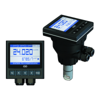
SOLID-STATE RELAY WIRING DIAGRAM
(FOR SSR1 AND SSR2)
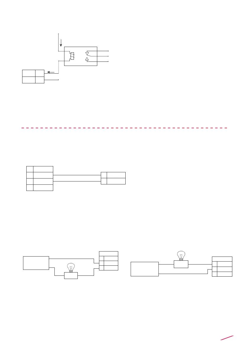
RELAY WIRING DIAGRAM
The alarm is OFF during normal
operation and goes ON according to
Relay settings
The alarm is ON during normal
operation and goes OFF according to
Relay settings
The alarm is off during normal
operation and goes ON according to
Relay setting.
If Imax > 50 mA use external Relay
Connection to other FLS Instruments
N.O.
N.O.
N.C.
COM
9
8
COM
External Relay
V= 12-24 VAC/VDC
Imax = 50 mA
Imax
Imax
+V
-V
FLS monitor
terminals
N.O.
COM
9
8
GND
DIR
FREQ IN6
5
6B
7 V+
Connection to an User
NC
10
11
12
RELAY 1
NO
COM
D
Alarm
AC or DC
Power
NC
10
11
12
RELAY 1
NO
COM
D
Alarm
AC or DC
Power
 Loading...