Quick Start Guide – OSI-RI-FL Smoke Detection System
Mounting the detector
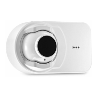
Remove detachable front rim cover.
To detach the Imager part from the backbox, loosen the 3 holding screws.
To provide cable access to the Termination Card of the Imager remove the cut-outs from the back, bottom or top
of the main assembly by using a sharp blade to cut around the circular discs.
Secure the back box directly onto the mounting surface using any suitable number of the 5 pilot holes in the
backbox.
Use appropriate fasteners to secure the back box component to the mounting surface.
Wire the Termination Card on the Imager:
• Wire the initiating device circuit on the Imager Termination Card using the addressable loop.
• Wire external power to the unit via the POWER terminals.
• Wire the Remote Indicator and/or remote test or reset units if required.
• Securely connect the wires to the plug-in terminals and engage in the receptacles at the back of the Imager.
• Switch on the heater if the installation requires so.
• Set the detector address using the rotary switches
• Re-attach the Imager to the back box
• Remove the protective lm from the lens surface of the imager (TBD).
• Connect power to the Imager.
3
4
This guide provides information on how to install the OSI-RI-FL Smoke Detection System.
Extensive product and critical product security information can be found in the OSI-RI-FL Installation Guide (Document
No. E56-6584 [33807]) available at www.relite.com.
The OSI-RI-FL system consists of an Imager and a reector.
Determine the positions of the Imager and reector components.
Make sure that the intended mounting locations meet the following criteria:
• Detector spacing must comply with local codes and standards
• Reector must be located within the Field of View (FOV) of the Imager
• Clear path between the reector and Imager
• Mounted well above the head-height of people and obstructions
• Avoid direct sunlight onto the units
The Imager and reector should be placed within a recommended distance below the ceiling. This value will
vary according to regional specications, geometry, and specic requirements for the installation. The distance
for at ceilings and basic spacing requirements (S) is shown in the following table.
Standard Distance from Ceiling Maximum Spacing (S)
NFPA 72 300 mm (12 in.) minimum 18.3 m (60 ft)
AS1670.1 25 to 600 mm (1 to 23.6 in.) 14 m (45.9 ft)
BS5839.1 25 to 600 mm (1 to 23.6 in.) 15 m (49.2 ft)
GB50166 300 to 1000 mm (11.8 to 39.4 in.) 14 m (45.9 ft)
For full information on spacing requirements, please refer to your local codes and standards.
1
Mount the reector using the drill template
Available in an appendix in the Product Guide.
2
Ex. Distances according to NFPA 72
1/2 S maximum
ReflectorTx/Rx
S
Tx/Rx
Reflector
16 ft. (5m) minimum
328 ft. (100m) maximum
1/4 S