Man-1144 Protection controller Operation manual issue 04 Page 10 of 11
5. Testing and commissioning
IMPORTANT – DISCONNECT ALL FIREPRO AEROSOL GAS GENERATORS
BEFORE TESTING.
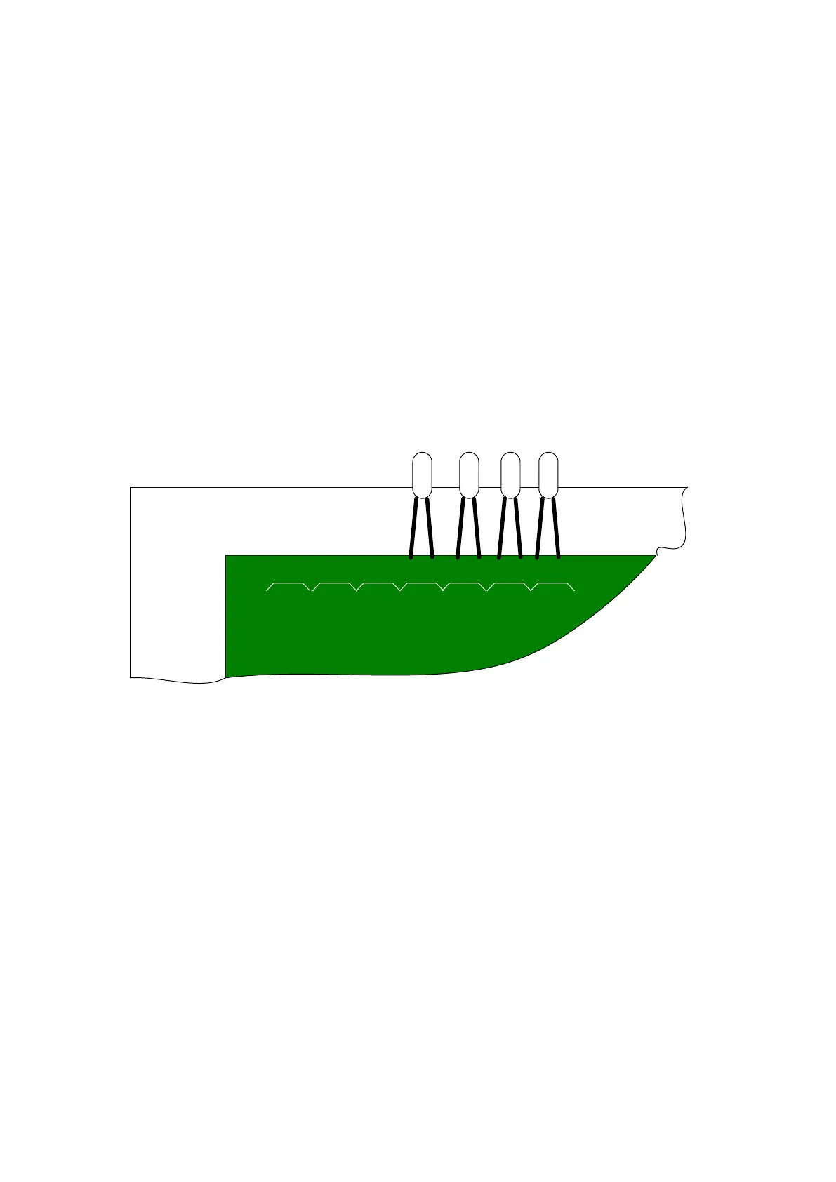
With all FirePro Aerosol Gas generators disconnected from the panel, ensure
that the test lamps that are supplied with the unit are fitted to terminals
FireproGEN1, FireproGEN2,
FireproGEN3 and FireproGEN4.
Do not leave any FirePro gas generators connected to the unit when
testing or these units will activate.
Figure 9 - Connections to Firepro
Gen outputs to test system.
Ensure that both jumper links are fitted in position “A” and trigger the detection
input by operating a smoke detector or linear heat detector. Ensure that the test
lamps connected to the FireproGEN terminals light immediately, the red fire
indicator on the front panel lights, the yellow fault indicator lights and the buzzer
sounds. Press the Buzzer Silence button to silence the buzzer and then the Reset
button to rest the system.
Disconnect the wiring to the detector and ensure that the yellow Fault LED on the
front panel and the internal yellow LED marked LED4 are lit and the buzzer
sounds. Press the buzzer silence button and ensure the buzzer silences. Re-
connect the detector wiring and ensure that the fault indication clears.
Disconnect one of the test lamps and ensure that the yellow Fault LED on the
front panel and the internal yellow LED marked LED5 are lit and the buzzer
sounds. Press the buzzer silence button and ensure the buzzer silences. Re-
connect the test lamp and ensure that the fault indication clears.
+ - + -
24V in 24V out Detection
+ -
Firepro
Gen1
Firepro
Gen2
Firepro
Gen3
Firepro
Gen4