Do you have a question about the Fireray 2000 and is the answer not in the manual?
Explains how the system detects smoke particles by measuring signal reduction in the beam path.
Details the alarm relay's configurable latching or non-latching reset behavior after smoke clears.
Describes the AGC circuit that compensates for signal degradation due to dirt build-up over time.
Lists various system failures that activate the fault relay, including power loss and misalignment.
Explains how to calculate lateral beam coverage increase for sloping ceilings based on pitch angle.
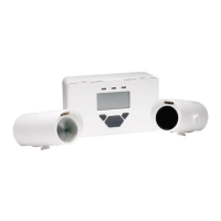
Covers parts confirmation, Control Unit mounting, and field wiring termination before main setup.
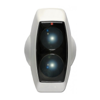
Details locating, fixing, and mounting the transmitter and receiver heads to brackets.
Introduces the mechanical and electronic alignment process for optimal beam detection.
Step-by-step guide using the Fireray 2000 Alignment Tool for beam alignment.
Step-by-step guide using a voltmeter to achieve correct beam alignment.
Procedure to adjust signal level potentiometer and confirm LED status after alignment.
Instructions for testing the alarm function using a test filter and observing Control Unit indication.
Details how to reset the system after an alarm test, depending on latching configuration.
Explains how to test the fault relay by blocking the beam and observing the fault LED.
Diagram illustrating the wiring connections for a typical single zone setup.
Lists key technical data including operating temperature, voltage, range, and dimensions.
Details switch settings for Alarm Latch and Sensitivity thresholds (25%, 35%, 50%).
Provides guidance on compliance with BS5839 part 5 and recommendations for threshold settings.
Advises on handling ESD sensitive devices within the Control Unit and general maintenance.
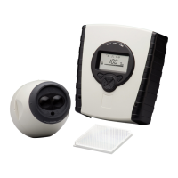
Lists all components included in the Fireray 2000 system package.
| Brand | Fireray |
|---|---|
| Model | 2000 |
| Category | Smoke Alarm |
| Language | English |