Fireray 2000 Installation Guide 22318.00.R 25.08.05
8
Technical Specifications
Data
Operating Temperature -20°C to +55°C
Operating Voltage 11.5 to 28 Volts DC
Transmitter Current < 1.6 – 5.6mA
Control Unit (includes Receiver) Quiescent Current < 8.5mA
Control Unit (includes Receiver) Alarm Current < 16.5mA
Control Unit (includes Receiver) Fault Current
<
16.5mA
Operating Range (distance between Transmitter and Receiver) 10 to 100 metres
Receiver tolerance to beam misalignment ± 4°
Transmitter tolerance to beam misalignment ± 1°
Fire alarm thresholds 1.25dB (25%), 1.87dB (35%), 3dB (50%)
Optical wavelength 880 nm (Infra red)
Control Unit max dimensions 215mm x 265mm x 88mm
Transmitter and Receiver max dimensions (inc. brackets) 83mm x 115mm x 135mm
Control Unit weight 1060 gms
Transmitter and Receiver weight (inc. brackets) 650 gms
Relay Contacts 2A 30 Volts DC resistive
Fireray 2000 Selectable Options
SWITCH OPEN CLOSED
ALARM LATCH Fire relay will automatically reset § Fire relay will not auto reset (latch)
COMP For BS5839 part 5 leave open. §
At the last AGC stage the Fireray will signal a fault,
but in the event of any further signal loss reducing
the signal to the selected threshold level, a fire alarm
will be signalled
At the last AGC stage the Fireray
will signal a fault, the fire relay will
be inhibited
25% 25% Alarm sensitivity selected
35% 35% Alarm sensitivity selected §
50% 50% Alarm sensitivity selected
NOTE: Select ONE Alarm sensitivity level only.
§
Factory Default Settings.
Application Notes
For full compliance with BS5839 part 5, use the 25% and 35% thresholds. The 50% threshold is only
recommended for hostile environments.
Service Notes
Control Unit contains ESD sensitive devices; appropriate care must be taken when handling internal
components.
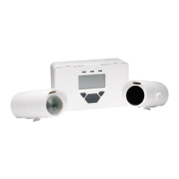
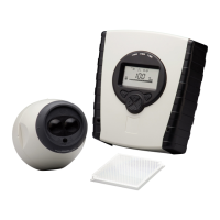
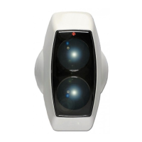
Parts List
1 Transmitter (clear lens).
1 Receiver (dark lens).
1 Control Unit.
2 Right angle brackets.
4 Bolts and washers.
1 Test Filter.
Fig 7
FIRE FIGHTING ENTERPRISES LIMITED
9 Hunting Gate, Wilbury Way, Hitchin
Hertfordshire SG4 0TJ England
Tel: +44 (0) 845 4024242
Fax: +44 (0) 845 4024201
Email: sales@ffeuk.com
www.ffeuk.com