DOCUMENT CONTROL NUMBER /
© 2001 Tyco Electronic Product Group PAGE 1 of 5
Registered Office: 19-21 Denmark Street, Wokingham, Berks RG40 2QE
FIRERAY 2000
01B-05-S1
02 1/01
EQUIPMENT:
PUBLICATION:
ISSUE No. & DATE:
«¥¥³¸¾¯¼¸«¾³¹¸«¶¥¶¾®¥¹·º«¸Ã
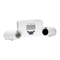
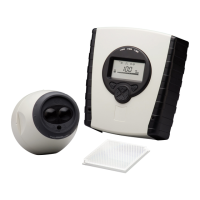
FIRERAY 2000 OPTICAL BEAM SMOKE DETECTOR
SERVICE AND MAINTENANCE
1. GENERAL
This document details the routine servicing and maintenance
procedures and provides a fault finding guide for the Fireray
2000 optical beam smoke detector.
The publication comprises:
Yearly checks
Fault finding guide
Alignment procedures
Testing
Spares list
When an incorrect response is obtained from a check, locate and
rectify the fault as described in Section 3.
When returning a faulty unit or PCB for repair, package it in the
bag that was used for its replacement.
2. ROUTINE CHECKS
The recommended routine checks must be carried out as stated.
2.1 YEARLY CHECKS
Inspect the Control Box, Transmitter and Receiver Units for
damage and ensure they are physically secure.
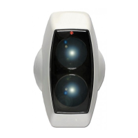
Clean the lenses on the Transmitter and Receiver Units. (If the
units are installed in a ‘clean area’ or dust free environment the
lenses need be cleaned only every two years).
Align and the test system as necessary.
3. FAULT FINDING GUIDE
This section details some of the possible faults which may occur
during testing of the Beam Detector Set. Most of the faults can
be easily rectified.
If the unit is suspected as faulty, retry the alignment procedure.
If the Beam Detector Set is still faulty replace the Beam
Detector Set with a new one.
If the problem persists, contact the Helpdesk at Sunbury.
Table 1 lists the internal controls and their function.
3.1 POSSIBLE CAUSES OF FAULT ALARMS
a) Receiver placed in the Reset state. Check that
the Test/Reset Switch (Fig. 1) is set to OFF.
b) The beam between the Transmitter and the
Receiver is obscured for more than 94% of the
beam area for one second. Check the beam is
not obscured or that the round glass areas on
the Transmitter or Receiver are dirty. Clean as
required.
c) Signal Level Control set too low at the
Receiver. Turn control (RV1) clockwise.
d) Receiver in Test mode. Ensure the Test/Reset
switch set to OFF.
e) Misalignment of the Transmitter and Receiver
detectors. Re-align as in the Alignment
procedure.
f) Loss of power. Check out the power supplies.
g) Source of infra-red setting of the alarm. Check
for sources of infra-red. For example: heat
emitting lights (eg, incandescent light bulbs),
direct sunlight, heaters and radiators at close
proximity to detectors.
CONTROL FUNCTION
Signal
Level (RV1)
Alters the gain of the received signal from
the transmitter. If the gain is set too low the
Beam Detector Set will not work correctly.
Do not set to maximum position in
NORMAL working mode.
Test / Reset
Switch
Sets the AGC level for the alignment checks
(ON) and arms the Beam Detector Set after a
fire alarm (OFF). Reset can also be done by
removing the power for 2 seconds or by
connecting the external reset input to 0V.
Test/Reset switch is normally in the OFF
position.
Table 1 Controls and their Function