PANEL SPECIFICATIONS
1. Certified to EN54 Pt2: 1997 and EN54 Pt4: 1997, and is suitable for
National installation requirements.
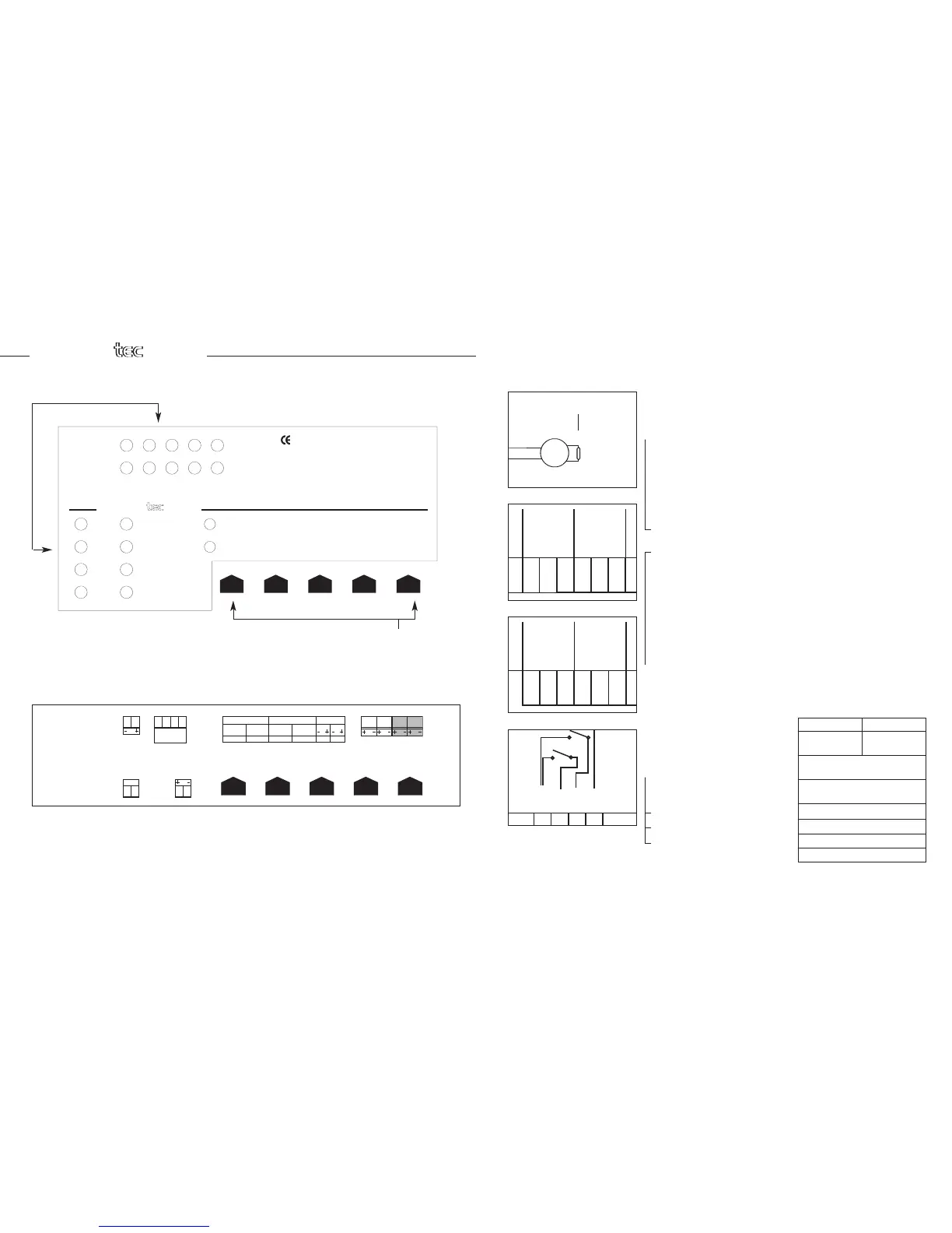
2. Five coded push buttons to control :-
RESET, EVACUATE, SILENCE ALARMS, SILENCE BUZZER, LAMP TEST,
WALK TEST, DISABLE and EXIT
3. LED Indicators:- General fire - General fault - 1/2/4 zone fire - 1/2/4
zone fault - Supply - Supply fault – Disabled - Alarm fault/disabled -
Test - System fault - Alarm silenced - Earth fault.
4. Zone end of line component that is polarised - Red end to Zn+ and
Black end to Zn-.
5. Two sets of auxiliary volt free contacts for fire and fault - Max.
current per contact set 2A at 30V dc.
6. Internal sounder - Minimum level 50dBA @ 1m.
7. Features:
USER ZONE AND ALARM DISABLE
USER LAMP TEST
ZONES MONITORED FOR OPEN CIRCUIT, SHORT CIRCUIT AND
DETECTOR REMOVAL
ALARM OUTPUTS MONITORED FOR OPEN AND SHORT CIRCUIT
AC AND DC POWER SUPPLY MONITORED
WALK TEST OPERATION
EARTH LEAKAGE DETECTOR AND SYSTEM FAULT MONITORING
1 & 2 zone 4 zone
8 Two sets of alarm outputs - 300mA max 1A max
total alarm output current
9. Power supply - Input 230v +10% -15% ac i/p 50Hz
Battery - Sealed lead acid 12v7Ahr
10. Auxiliary fused output 250mA
(fuse monitored) 24v
11. Class change input (CC) YES
12. Pulse Alert input (BA) YES
13. Open collector - FIRE output (CF) YES
14.
Volt free relay - FAULT output
YES
S
YSTEM FAULTSYSTEM FAULTSYSTEM FAULT
EARTH FAULTEARTH FAULTEARTH FAULT
SUPPLYSUPPLYSUPPLY
ZONESZONESZONES
222111
3
33
444
SUPPLY FAULTSUPPLY FAULTSUPPLY FAULT
DISABLEDDISABLEDDISABLED
ALARM FAULT/
DISABLED
ALARM FAULT/ALARM FAULT/
DISABLEDDISABLED
T
ESTTESTTEST
ALARM
SILENCED
ALARMALARM
SILENCEDSILENCED
GENERAL FAULTGENERAL FAULTGENERAL FAULT
GENERAL FIREGENERAL FIREGENERAL FIRE
F
AULT / DISABLE
/ TEST
F
AULT / DISABLEFAULT / DISABLE
/ TEST/ TEST
FIREFIREFIRE
SILENCE
B
UZZER
SILENCESILENCE
B
UZZERBUZZER
SILENCE
ALARMS
SILENCESILENCE
ALARMSALARMS
EXITEXITEXIT
EVACUATEEVACUATEEVACUATE
LAMP TESTLAMP TESTLAMP TEST
RESETRESETRESET
RESETRESETRESET
W
ALK TESTWALK TESTWALK TEST DISABLEDISABLEDISABLE
333222 444 555
E
N54-2 : 1997EN54-2 : 1997EN54-2 : 1997 EN54-4 : 1997EN54-4 : 1997EN54-4 : 1997
SILENCE
BUZZER
SILENCESILENCE
BUZZERBUZZER
111
tec tec
EN54EN54EN54
FIREFIREFIRE
Coded Push Buttons
LED indicators
This manual provides the necessary guidance for the correct installation and commissioning of the
FIREtec EN54 1, 2 & 4 zone (EN54 Pt2: 1997 and EN54 Pt4: 1997 approved) fire panels. Persons
carrying out system design and installation should be competent and familiar with the relevant code
of practice relating to the installation of fire detection and alarm systems within buildings.
Key
NO Normally Open Contact
NC
Normally Closed Contact
C Common Contact
AL Alarm Line
CC
Class Change Input
BA Pulse Alert Input
CF Common Fire Output
COM
Common 0v
AUX Auxiliary Outputs
 Loading...