RED
BLACK
BLACK
RED
RED
BLACK
RED
BLACK
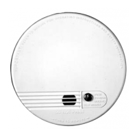
Fire Alarm Control Panel Wiring
UL
Listed
Fire
Alarm
Control
Unit
5
15
5
15
13
14
13
14
Firex Detector
#1
Firex Detector
#2
EOL
End
of
Line
Fig. 1
12
19
19
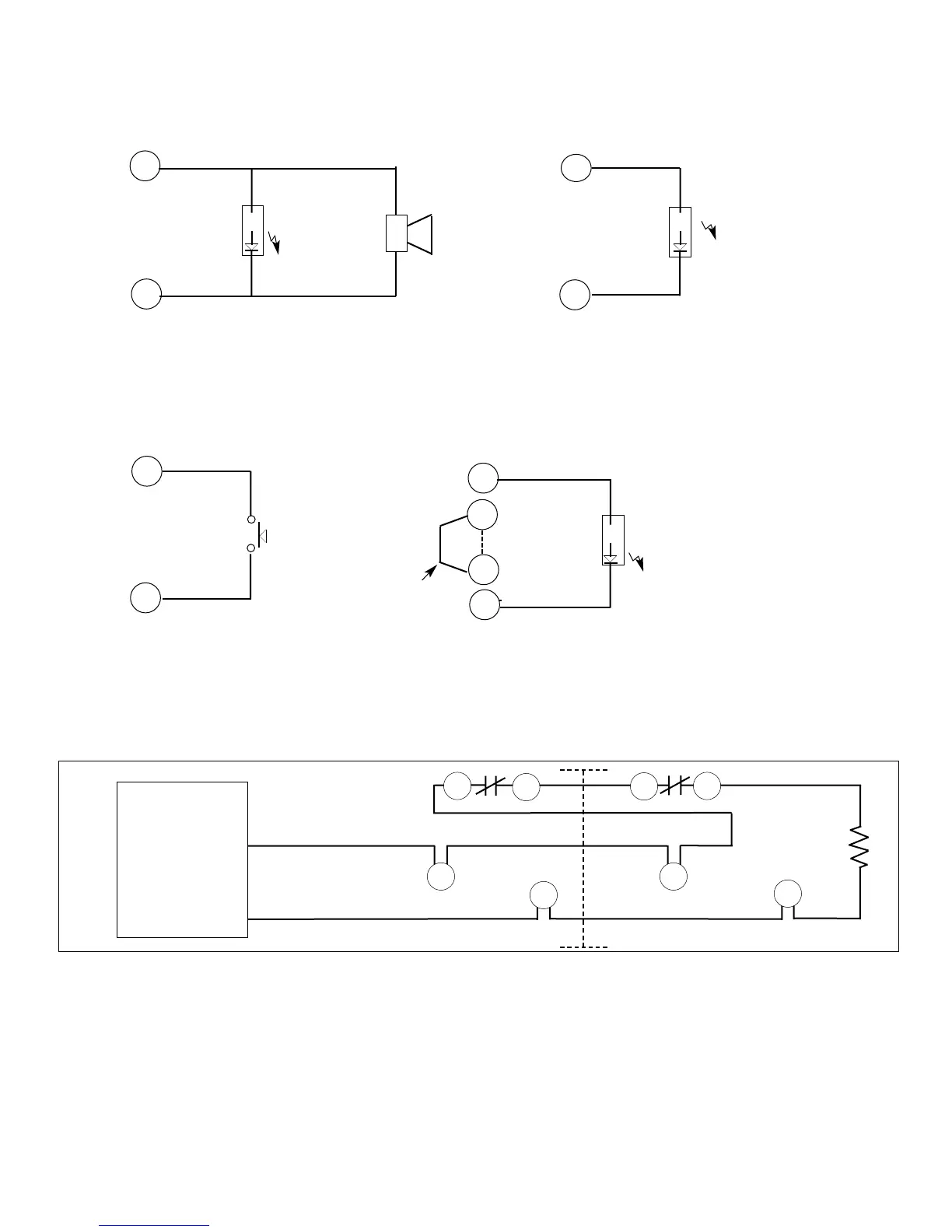
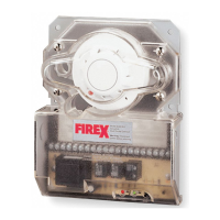
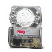
REMOTE ACCESSORY WIRING
vvv
vvv
1
20
4
19
vvv
15
20
YELLOW
“TROUBLE
LED
KEY OR
PUSH BUTTON
“TEST/RESET
SWITCH
RED
“ALARM”
LED
AND
OR
HORN/
STROBE
_
_
GREEN
PILOT
LED
TROUBLE CONTACTS
CANNOT BE CONNECTED
TO FIRE ALARM PANEL
WHEN USING THIS
OPTION
JUMPER
HEAD OR COVER
REMOVAL
TEST / RESET
ALARM
(WHEN NOT INTERCONNECTED)
PILOT
2
Remote Accessories Approved For Use With This Detector
535 Remote Alarm 542 Remote Alarm, Pilot, Horn, key-operated Test/Reset Switch
536 Remote Alarm, push button Test/Reset Switch 543 Remote Alarm, Pilot, Horn
537 Remote Alarm, Pilot, push-button Test/Reset Switch 544 Remote Alarm, Trouble, Pilot, Horn, key-operated Test/Reset Switch
538 Remote Alarm, key-operated Test/Switch 545 Horn/Strobe, red housing, clear cover
539 Remote Alarm, Pilot, key-operated Test/Reset Switch 546 Horn/Strobe, white housing, opaque cover
540 Remote Alarm, Pilot 547 Horn/Strobe, white housing, clear cover
541 Remote Alarm Horn
AP 186 MA 2650-760; 01/01