EasyManua.ls Logo

Fireye FLAME-MONITOR E110 User Manual

Fireye FLAME-MONITOR E110
48 pages
To Next Page IconTo Next Page
Page #1 background imageLoading...
Page #1 background image
1
®
DESCRIPTION
The Fireye
®
E110 FLAME-MONITOR™ System is a microprocessor based burner management
control system designed to provide the proper burner sequencing, ignition and flame monitoring pro-
tection on automatically ignited oil, gas, and combination fuel burners. In conjunction with limit and
operating controls, it programs the burner/blower motor, ignition and fuel valves to provide for
proper and safe burner operation. The control also provides current operating status and lockout
information in the event of a safety shutdown. The manner in which this information is displayed is
dependent on the type of programmer (EP or EPD) and display module (ED510 or ED500).
*
Refer
to Flame-Monitor PROGRAMMER SELECTION later in this document for the various combina-
tions of programmer and display modules.
The E110 consists of the EB700 chassis, dust cover, and shortened mounting screw (P/N 48-1836).
The display module (ED510), if required, must be ordered separately. Interchangeable programmer
and flame amplifier modules allow for complete versatility in selection of control function, timing,
and flame scanning means. Functions such as pre-purge, recycling interlocks, high fire proving inter-
lock, and trial for ignition timing of the pilot and main flame are determined by the programmer
module. The E110 Flame-Monitor can be used with ultra-violet, auto-check infrared, flame rod, or
self-check ultraviolet flame scanners by choosing the proper amplifier module.
The eighteen (18) terminal wiring base allows for many functional circuits including motors, valves,
and ignition transformers as well as multiple interlocks such as high purge, low purge, fuel valve and
running interlock circuits. The E110 uses the same wiring base as the Fireye E100 Flame-Monitor
control, D Series and C Series Controls and is directly interchangeable with most models without
rewiring.
Additional functions of the Flame-Monitor system include:
A non-volatile memory which allows the control to remember its history and present position
even when power is interrupted.
A constant flame signal read-out via display module or 0-10 VDC output (EPD
programmers only).
Read-out of main fuel operational hours and complete cycles via display module.
Modbus communications via RS485 multi-drop link.
Dipswitches located on the EP programmer to allow selectable purge time.
A run/check switch which allows the operator to stop the program sequence in any of three dif-
ferent positions (Purge, PTFI, or Auto).
Remote Display Capability.
Annunciate 16 additional interlocks using E300 Expansion Module.
*
The ED500 display was the predecessor of the ED510 display and uses an older design. It does not have the latest features
of the ED510 display module.
E110 FIREYE
FLAME-MONITOR
BURNER MANAGEMENT CONTROL
FOR USE WITH THE
MICROPROCESSOR-BASED
EP AND EPD STYLE
PROGRAMMER MODULES
E-1101
MARCH 28, 2013
APPROVED
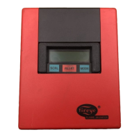
E110 with ED510 Display Module

Table of Contents

Question and Answer IconNeed help?

Do you have a question about the Fireye FLAME-MONITOR E110 and is the answer not in the manual?

Fireye FLAME-MONITOR E110 Specifications

General IconGeneral
Enclosure RatingNEMA 1
TypeFlame Monitor
Input Voltage120 VAC
Power Consumption10 VA
Operating Temperature-40°F to +140°F (-40°C to +60°C)

Summary

DESCRIPTION

FLAME-MONITOR SPECIFICATIONS

Operating Temperature Limits

Defines the acceptable operating temperature range for the control and associated components.

Load Ratings

Details the electrical load ratings for various terminals and connections.

ELECTRICAL RATINGS AND APPROVALS

SELECTION GUIDES

Applicable Bulletins

Lists relevant technical bulletins for E110 Flame-Monitor system components.

Flame Amplifier and Scanner Selection

Guides for choosing the correct flame amplifier and scanner for the application.

Ordering Information and Component Selection

Details on ordering the E110 Flame-Monitor and its required system components.

PROGRAMMER AND DISPLAY MODULES

Flame Monitor Programmer Selection

Explains how to select the appropriate programmer module based on application needs.

Programmer and Display Module Compatibility

Information on compatible programmer and ED510 display module combinations.

INSTALLATION AND WIRING

Control Installation and Preparation

Steps for installing the control unit, including wiring base and pre-installation checks.

Wiring Diagrams and Grounding Rules

Provides suggested wiring diagrams and essential grounding guidelines.

Scanner Installation Guidelines

Best practices for installing various types of scanners, including UV and infrared.

OPERATION AND TESTING

Control Operation and Start-Up

Details the normal operating sequence, start-up process, and programming logic.

Shutdown Procedures

Describes the normal shutdown sequence and states of the control.

Testing Procedures

Covers installation, operational, voltage, and checkout testing procedures.

MESSAGES, DIAGNOSTICS, AND SUB-MENUS

ED510 Display Messages

Lists and explains all run, hold, lockout, and check messages displayed by the ED510.

System Sub-Menus and Diagnostics

Details system sub-menus for historical info, diagnostics, and configuration.

MAINTENANCE AND TROUBLESHOOTING

Scanner Maintenance

Instructions for cleaning, maintaining, and troubleshooting scanners.

General Maintenance Checks

Covers contacts, electrical noise, humidity, periodic safety checks, and rotation.

COMMUNICATIONS AND WARRANTIES

Communications Protocol

Details the Modbus RTU protocol used for communication with the Flame-Monitor.

Warranties

Information on Fireye product warranty terms and conditions.

Related product manuals