Do you have a question about the Fireye PPC6000 Series and is the answer not in the manual?
Provides general specifications like supply voltage, dimensions, and weight.
Details servo-motor control type, quantity, accuracy, and response time.
Describes controlled shutdown and safety shutdown output specifications.
Specifies alarm output type, minimum and maximum current, and voltage.
Details low voltage and high voltage digital inputs and their configurations.
Outlines specifications for 0-5V and 4-20mA pressure/temperature inputs.
Describes the RS485 interface and optional isolated RS485 options.
Lists specifications for the optional oxygen probe interface unit.
Details specifications for the optional ambient air temperature unit.
Provides specifications for the VSD daughter board, including inputs and outputs.
Details specifications for various Fireye servo motors, including torque and VA rating.
Lists specifications for the optional oxygen probe interface unit, including voltage and protection category.
Provides specifications for the optional ambient air temperature sensor.
Lists standards and directives the product has been tested against.
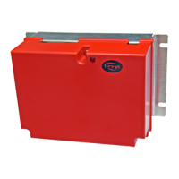
Lists part numbers and descriptions for the controller, displays, and servo motors.
Provides dimensions and mounting clearances for the PPC6000 control unit.
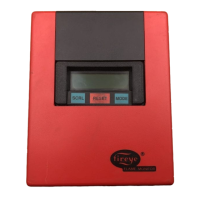
Details the panel cut-out and mounting procedure for the display module.
Specifies mounting requirements and enclosure details for the oxygen probe interface.
Covers the oxygen trim function, probe description, and installation guidelines.
Explains the function and correct setting of circuit board option links.
Provides general wiring guidelines, including shielded wire requirements.
Outlines motor requirements, connection method, and available models.
Warns about setting servo-motor direction correctly to avoid damage and ensure proper operation.
Emphasizes the importance of securely connecting motors to valve shafts for safe operation.
Details securing the feedback potentiometer to prevent disconnection from the motor shaft.
Provides a procedure for setting microswitch positions to ensure correct closed and open positions.
Guides on replacing servomotors, including determining direction and serial numbers.
Describes the 2-line display and membrane keypad functions.
Details the stages of the burner start-up and shut-down sequence.
Explains conditions leading to non-volatile lockouts, which are not cleared by power removal.
Covers burner modulation modes (Remote, Local) and PID functions.
Explains the necessity of entering commission mode for changing settings and safety precautions.
Covers option parameters and setpoints used for configuring the burner and boiler.
Details navigation within the commissioning process and symbols used.
Explains the functions and displays of the touchscreen interface.
Describes how fault numbers are displayed with prefixes indicating status.
Provides steps for addressing faults, including muting alarms and clearing faults.
Explains that faults stored in non-volatile memory persist after power loss.
Defines fault subsets as additional information about fault type or burner status.
Lists common faults, their causes, and descriptions.
Explains how to use the engineer's key to view system variables and fault details.
Offers general troubleshooting guidance for display and general issues.
Lists common startup problems and their suggested solutions.
Addresses common commissioning issues and their resolution steps.
Details troubleshooting steps for modulation-related problems.
Provides solutions for inverter-related issues, including start-up and control problems.
Describes the system configuration for controlling inverter drives with PPC6000.
Explains the control method for drives, including start-up and modulation.
Details the criteria and steps for setting up an inverter for use with the PPC6000.
Provides step-by-step instructions for configuring the PPC6000 to work with an inverter drive.
Describes the oxygen trim function and the NX2012 oxygen probe.
Covers the installation procedure for the oxygen probe, including mounting guidelines.
Details specific mounting instructions and considerations for the oxygen probe.
Provides a step-by-step guide for calibrating the oxygen probe.
Details the procedure and requirements for calibrating the oxygen probe.
Explains how to test the oxygen probe filter without removing it from the flue.
Provides safety precautions and steps for removing the oxygen probe from the flue.
Guides on replacing the oxygen probe filter assembly.
Details the procedure for replacing the flue thermocouple mounted on the probe.
Lists common inverter problems and their suggested solutions.
Explains the PID control concept and how to adjust proportional, integral, and derivative terms.
Provides guidelines for setting up combustion profiles and entering data.
Explains how efficiency is calculated and the parameters required for accurate results.
Introduces Abacus software for programming PPC6000 and NX6100 controls.
Describes the function block toolbar and its buttons for creating schematics.
Explains how to place function blocks onto the schematic page.
Guides on selecting and moving link lines to adjust the schematic appearance.
Shows the circuit board connections for the optional NXIATS Inlet Air Temperature Sensor.
Details the circuit board connections for the PPC6000 VSD daughter board.
Illustrates the circuit board connections for the optional NX02INT Oxygen Probe Interface.
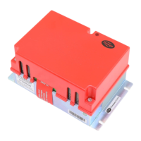
Shows the jumper and fuse detail on the PPC6000 unit backplate.
| Category | Controller |
|---|---|
| Display | LCD with backlight |
| Outputs | Multiple configurable outputs |
| Communication | Modbus RTU |
| Relay Outputs | Configurable relay outputs |
| Analog Inputs | Configurable analog inputs |
| Digital Inputs | Configurable digital inputs |
| Enclosure Rating | NEMA 4X |