Connecting the FA-SYNC-2:
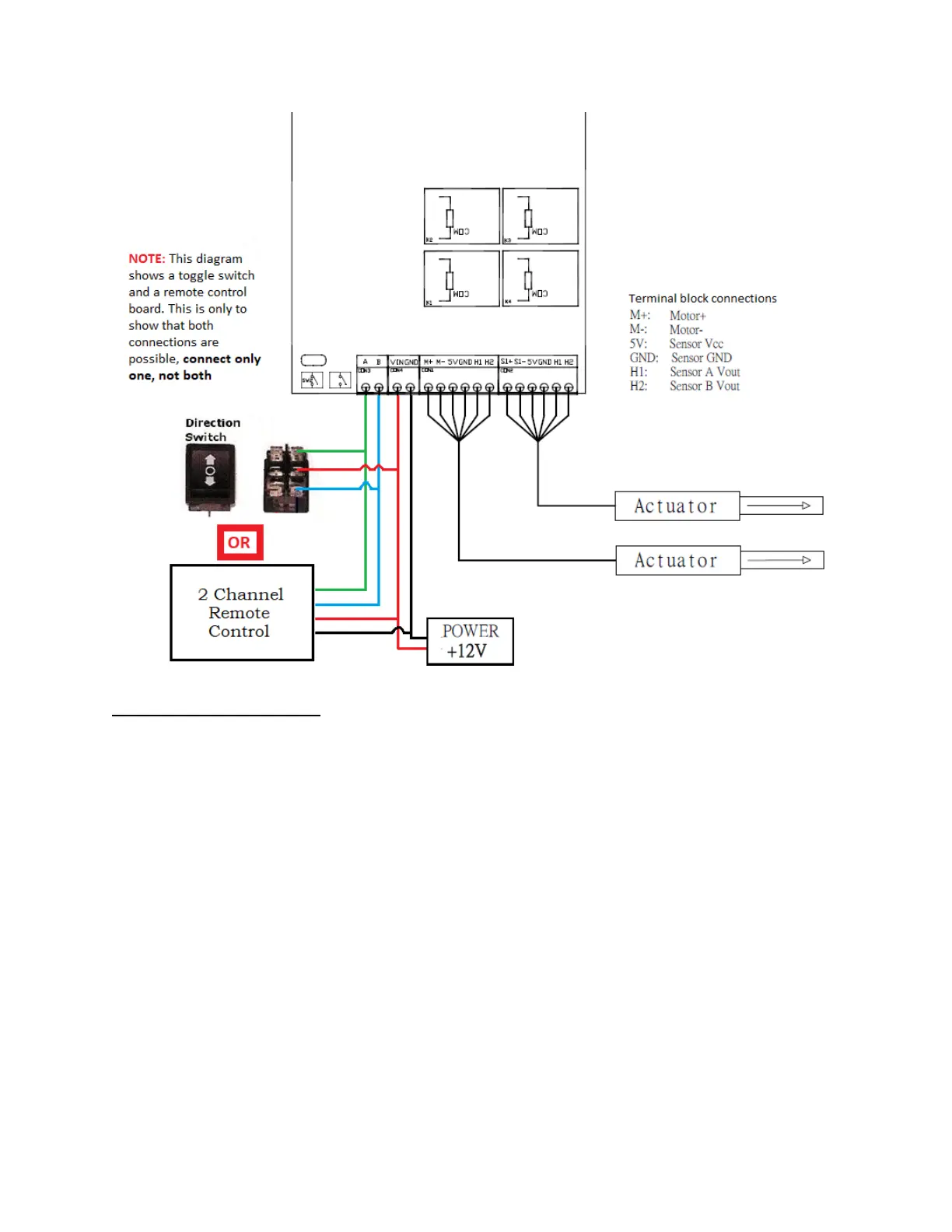
The leftmost, two-pin, green terminal block plug (labeled A & B) is for user input. Connect
either a toggle switch or Firgelli’s 2 Channel Remote Control Board. NOTE: the diagram shows
both a toggle switch and a remote control board, this is only to show that both connections are
possible, connect only one, not both.
The next two-pin, green terminal block plug (labeled VIN & GND) is for a 12V power input. This
control board requires 12V at 10 amps. WARNING: do not reverse the polarity of the input
voltage; the unit will be damaged permanently if polarity is reversed.
The remaining six-pin, green terminal block plugs are for your actuators. Connect wires from
each actuator to their respective terminal blocks as per the table on the following page.