WARNING: Wire color is subject to change. Confirm color by inspecting sticker on actuator.
Calibrating the FA-SYNC-4:
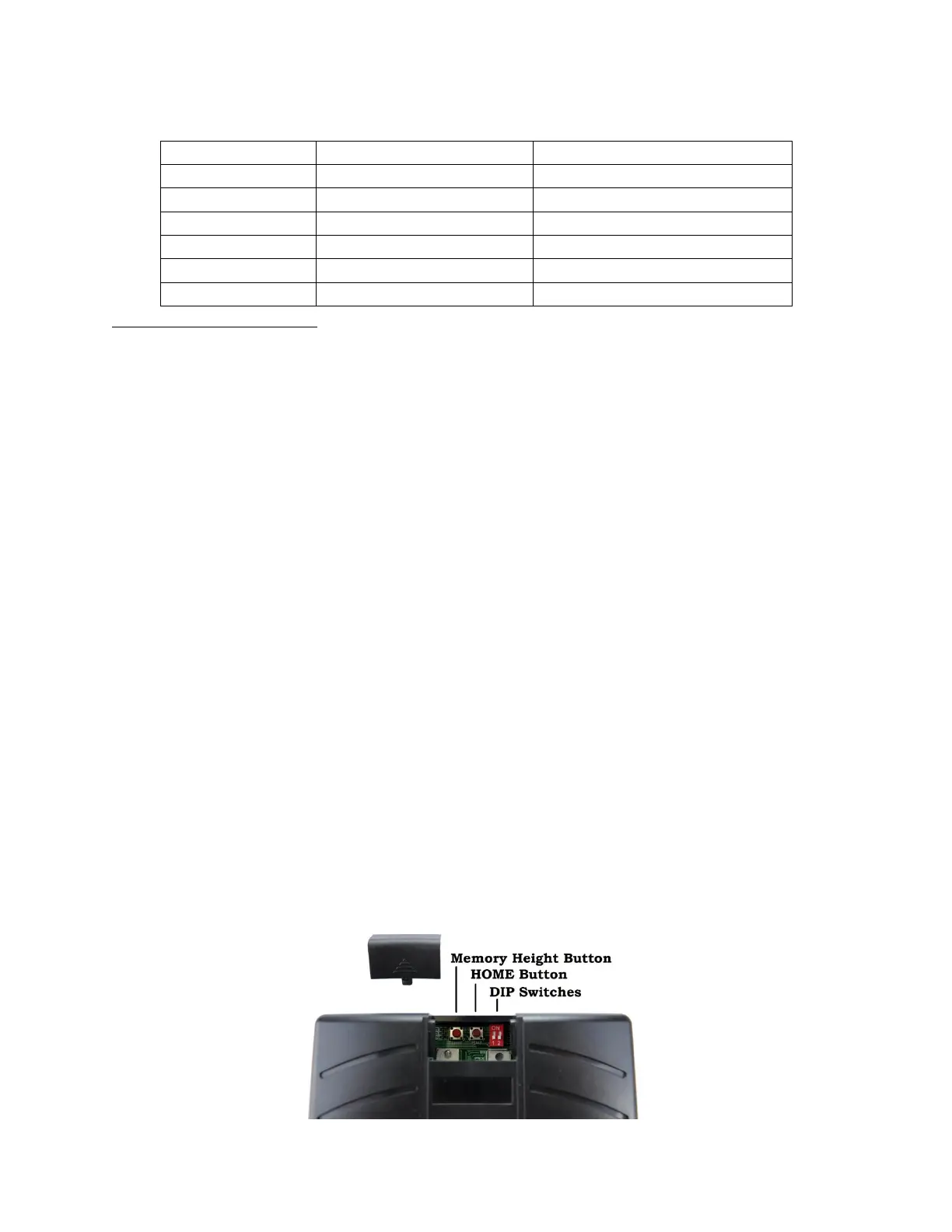
Remove the black plastic slide at the top of the control board. Inside are two momentary push
buttons and two DIP switches (see picture below).
➢ If only two actuators are connected set the DIP switches labeled “1” and “2” to “ON”
➢ If three actuators are connected set the DIP switch labeled “1” to “OFF” and “2” to “ON”
➢ If four actuators are connected set the DIP switches labeled “1” and “2” to “OFF”
Once all wires are connected and the DIP switches have been set, the board must be calibrated
to the specific type of actuator you are using. To do this, the control board will count the
number of signal pulses from the encoder inside the actuator during a complete actuation
cycle. Follow the procedure:
➢ Ensure actuators are laying on a table and not connected to your load or application
➢ Confirm wiring connections
➢ Press and quickly release the right-most momentary switch labelled “HOME”. You will
hear the relays on the circuit board click once and the actuators will all begin retracting
(if they start extending instead of retracting simply reverse the order of the M+ and M-
connections)
➢ When all actuators are fully retracted the relays will click several times. Once they stop,
press and hold the “HOME” button until the actuators begin extending.
➢ The actuators will fully extend, pause, and then fully retract. Once retracted you will
again hear the relays click several times.
➢ The FA-SYNC-4 board is now calibrated and your actuators can be installed in your
application. The control board will remember the calibration settings even if power is
disconnected during installation.
 Loading...