Connecting the FA-SYNC-4:
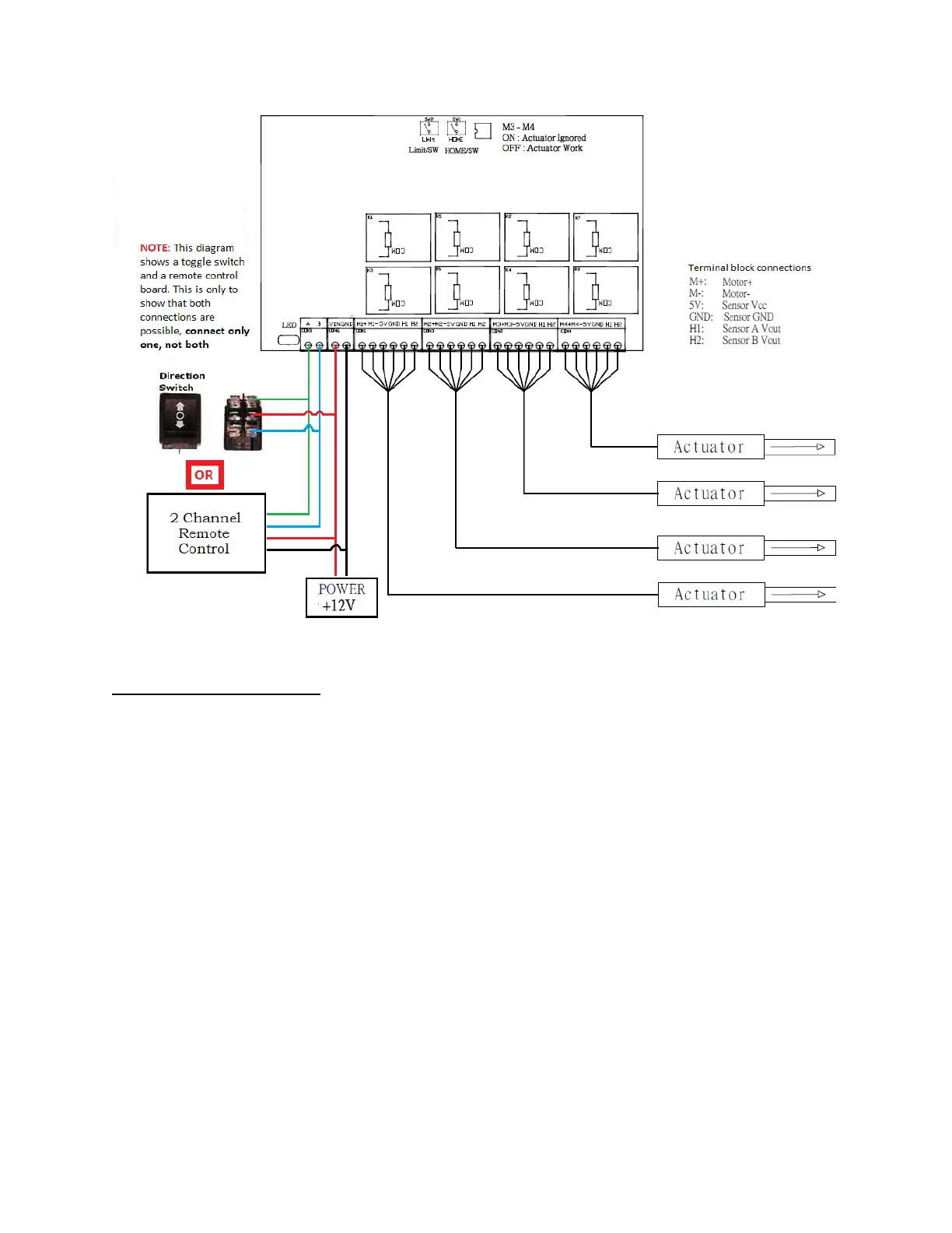
The leftmost, two-pin, green terminal block plug (labeled A & B) is for user input. Connect
either a toggle switch or Firgelli’s 2 Channel Remote Control Board. NOTE: the diagram shows
both a toggle switch and a remote control board, this is only to show that both connections are
possible, connect only one, not both.
The next two-pin, green terminal block plug (labeled VIN & GND) is for a 12V/24V power input.
This control board requires at least a 12V at 20 amps when all four actuators are connected. As
such, we recommend using Firgelli’s AC to DC Power Supply 12V 30A. WARNING: do not reverse
the polarity of the input voltage; the unit will be damaged permanently if polarity is reversed.
The remaining six-pin, green terminal block plugs are for your actuators. If using less than 4
actuators leave the terminal blocks on the right side of the board disconnected. Connect wires
from each actuator to their respective terminal blocks as per the table on the following page.