This document is a user guide for First Solar Series 6™ Modules, specifically models FS-6XXX and FS-6XXXA, as well as Series 6 Plus Modules (FS-6XXXA-P and FS-6XXXA-P). These are advanced photovoltaic (PV) modules designed for system designers, installers, and maintenance personnel, featuring an anti-reflective coating (ARC) on the front surface. The Series 6 Modules and Series 6 Plus Modules are electrically compatible.
Function Description:
The First Solar Series 6™ Modules are designed to convert sunlight into electricity, forming the core component of a solar PV system. They are engineered for long operating life and high energy yield, suitable for various installations, operations, and maintenance scenarios. The modules are designed to be integrated into ground-mounted and rooftop PV systems, providing a reliable source of renewable energy.
Important Technical Specifications:
The Series 6 Modules are designed for 1000 V systems at altitudes up to 5000 m (16404 ft) per IEC 61730 and 3000 m (9842 ft) per UL 61730. Series 6 Plus Modules are designed for 1500 V systems at altitudes up to 3000 m (9842 ft) per IEC 61730 and 2000 m (6561 ft) per UL 61730. The maximum overcurrent protection rating is 5.0A, as defined by UL 1703 and a maximum overcurrent protection rating of 5.0A as defined by UL 61730/IEC 61730-1/IEC 61730-2. Series 6 Modules are designed to comply with and provide module overcurrent protection consistent with local codes.
The modules exhibit specific electrical characteristics at Standard Test Conditions (STC), including:
- Pmax (W): Ranging from 390.0 W to 460.0 W, with a tolerance of (+/-5%).
- Vmax (V): Ranging from 173.9 V to 188.8 V.
- Imax (A): Ranging from 2.24 A to 2.44 A.
- Voc (V): Ranging from 214.8 V to 222.9 V.
- Isc (A): Ranging from 2.49 A to 2.59 A.
- Max System Voltage: 1500 VDC.
- Max Series Fuse: 5.0A.
Temperature characteristics are also provided:
- Module Operating Temperature Range: -40 to +85 °C.
- Temperature Coefficient of Pmax (T_Pmax): -0.32% / °C (Temperature Range: 25 °C to 75 °C).
- Temperature Coefficient of Voc (T_Voc): -0.28% / °C.
- Temperature Coefficient of Isc (T_Isc): +0.04% / °C.
Mechanical specifications include:
- Length (A): 2009 mm +3/-1 mm (79.1 +0.11/-0.04 in) for FS-6XXX / FS-6XXXA, and 2024 mm +3/-1 mm (79.7 +0.11/-0.04 in) for FS-6XXX-P / FS-6XXXA-P / FS-6XXXA-P-I.
- Width (B): 1232 mm ± 2 mm (48.5 ± 0.08 in) for FS-6XXX / FS-6XXXA, and 1245 mm ± 2 mm (49.0 ± 0.08 in) for FS-6XXX-P / FS-6XXXA-P / FS-6XXXA-P-I.
- Height (C): 49 mm ± 1 mm (1.9 ± 0.04 in) for FS-6XXX / FS-6XXXA, and 45.5 mm ± 1 mm (1.8 ± 0.04 in) for FS-6XXX-P / FS-6XXXA-P / FS-6XXXA-P-I.
- Total Area: 2.47 m² (26.5 ft²) for FS-6XXX / FS-6XXXA, and 2.52 m² (27.1 ft²) for FS-6XXX-P / FS-6XXXA-P / FS-6XXXA-P-I.
- Module Weight: 34.5 ± 1 kg (76 ± 2.2 lbs) for FS-6XXX / FS-6XXXA, and 34.9 ± 1 kg (76.9 ± 2.2 lbs) for FS-6XXX-P / FS-6XXXA-P / FS-6XXXA-P-I.
- Fire Performance: Type 19: Class A Spread of Flame / Class C Burning Brand for FS-6XXX / FS-6XXXA, and Type 19: Class A Spread of Flame / Class C Burning Brand for FS-6XXX-P / FS-6XXXA-P / FS-6XXXA-P-I.
The modules are tested and certified per IEC 61730-1/IEC 61730-2 and meet Class II requirements for 1500 VDC systems. They are also certified per IEC 61215-1/IEC 61215-1-2/IEC 61215-2 for a maximum system voltage of 1500 V.
Usage Features:
- Installation & Mounting: The modules require careful handling and trenching prior to installation to minimize exposure to dust. They should be installed in a clean environment, free from chemicals or materials used for on-site dust control or weed control. Modules should not be sprayed, splashed, or drifted onto the surface.
- Mounting Locations & Load Ratings: The mounting system design must provide adequate support for the module to prevent load damage. Structures must not come into direct contact with the surface or edges of the module glass or center cross brace(s). Modules can be secured to the support structure with top (front side) mounting clamps or by frame slots, known as SpeedSlots.
- Top Mounting: Top mounting clamps must have a uniform frame engagement area of 9 mm (0.35 in) minimum width on the top ledge and 30 mm (1.18 in) minimum length.
- SpeedSlot Mounting: SpeedSlot clamps must extend 10 mm (0.39 in) beyond the inner edge of the frame, or have a retention feature to prevent module frame dislodgement under load. SpeedSlot clamps must be at least 12 mm (0.47 in) wide from attachment point through the 10 mm (0.39 in) extension or until point of retention feature.
- Module Orientation: PV module performance modeling software, such as PlantPredict, should be used to determine the optimum orientation and tilt angle for each location. Mount modules in portrait orientation for applications where row-to-row shading could occur. Landscape orientation is permitted only in flat mount applications where the module long edge is not completely shaded and when compliant with Section 7.7 Module Shading Considerations.
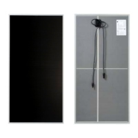
- Wire Management: All wire management must comply with applicable NEC/IEC codes and standards. The module frame includes four 5.6 mm (0.22 in) wire management holes in locations depicted in Figure 10. The maximum cable weight carried by each module in totality may not exceed 3.5 kg (7.6 lbs).
- Electrical Interconnection: All electrical components must have an operating voltage range that matches the maximum power point of the array, and be capable of operating the array at the maximum power point at all times. Short circuit operation is permitted only during short duration system safety testing or in fail-safe system states. Series 6 Modules are pre-configured with industry standard connectors that are "touch proof" with all live parts protected against accidental contact and protected against polarity reversal.
- Inverter Compatibility: Series 6 Modules are compatible with a range of string, central, transformer, and transformerless inverters. When connecting modules or module strings in series, ensure inverter ratings are appropriate.
- Grounding Method: Series 6 Modules are designed to be used in negative-grounded systems. Modules must not be subjected to negative voltage bias conditions that can occur in voltage floating or bi-polar systems (subjecting modules to conditions that could drive potential induced degradation). Grounding/bonding devices must meet the IEC 61730-2 the pass/fail criteria of a 100 mΩ resistance.
Maintenance Features:
- Regular Inspection and Maintenance: A regular inspection and maintenance schedule should include, but is not limited to:
- Annually at a minimum, inspect modules for any signs of damage or broken glass. Replace broken modules immediately.
- Keep modules free from debris, particulates, or large volumes of snow to maximize system performance.
- Ensure the module surface pressure is at or below the design load by removing snow.
- Inspect wiring and wire management periodically.
- Inspect and confirm electrical connections are tight and corrosion free.
- Avoid using brush/ground maintenance tools (Example: weed trimmer, brush cutter, etc.) that could send projectiles toward module glass.
- Module Cleaning Guidance: Modules require cleaning in most climates. Installed modules may collect a light layer of dust and/or dirt (soiling) over time and periodic rainfall should be sufficient to remove light soiling in most cases. In locations with heavy soiling, properly timed module cleaning can improve energy yields.
- Acceptable Wet Cleaning: When using water, RO water provides the best results. When RO water is not available, tap water with low mineral content (total hardness <75 mg/L) or deionized water may be used. Calcium should not exceed 75 mg/L. Fresh water (TDS < 1500 mg/L) may be used to clean the modules. If needed, a mild, non-abrasive, non-caustic detergent with a final fresh water and detergent solution mix between 6.5 < pH < 8.5 at 25 °C may be used. Water must be free of floating oil or other immiscible liquids, floating debris, excessive turbidity, and objectionable odors. Chlorides should not exceed 250 mg/L and water conductivity should be < 250 mS/cm. Water temperature must be ± 20 °C from module temperature applied with water pressure <35 bar (500 psi) at nozzle.
- Prohibited Wet Cleaning: Wet contact cleaning (squeegees, sponges, cloths, etc.), which includes any simultaneous combination of water and scrubbing/wiping, is prohibited. Pressurized water sprayed directly at sealed interfaces of modules (junction box, edge seal, and connectors) is prohibited. Hard water (>75 mg/L total hardness) is prohibited. Abrasive cleaners or degreasers, cleaning solutions containing hydrochloric acid, D-Limonene, ammonia, or sodium hydroxide are prohibited.
- Acceptable Dry Cleaning: Dry cleaning with soft cloths or mops is allowed up to 12 times annually. Excessively soiled spots on modules (i.e., bird droppings) may be spot cleaned with soft cloth or mop and water if necessary for localized cleaning only (<10% of module area).
- Prohibited Dry Cleaning: Backside cleaning; potential for accidental stress to lead wire or junction box is prohibited. Dry cleaning with anything other than soft cloths or mops (i.e. bristle brushes, sponges, or squeegees) is prohibited.
- Module Disposal: Modules may be recycled or disposed of in accordance with applicable local requirements. Information for recycling programs can be found at www.firstsolar.com/recycling.