Pin 6 Black/White - Auxiliary Input 2 – This wire functions as a negative (-) instant trigger input. It is
selectable based on option 2-13. It can be changed to a negative disarm or negative drive lock
control. Please refer to the option tables for details. This wire is required for ignition controlled
door locks.
Pin 7 Yellow
- Auxiliary 1 Output – This wire provides a customized timed output for triggering extra
sensors and/or features such as power sliding doors or power windows. The settings can be
changed via option 2-08. To set a custom timed output you must use option setting 4 as well as
an OP500 Option Programmer.
Pin 8 Yellow/White
- Auxiliary 2 Output – This wire provides a customized timed output for triggering
extra sensors and/or features such as power sliding doors or power windows. The settings can be
changed via option 2-09. To set a custom timed output you must use option setting 4 as well as
an OP500 Option Programmer.
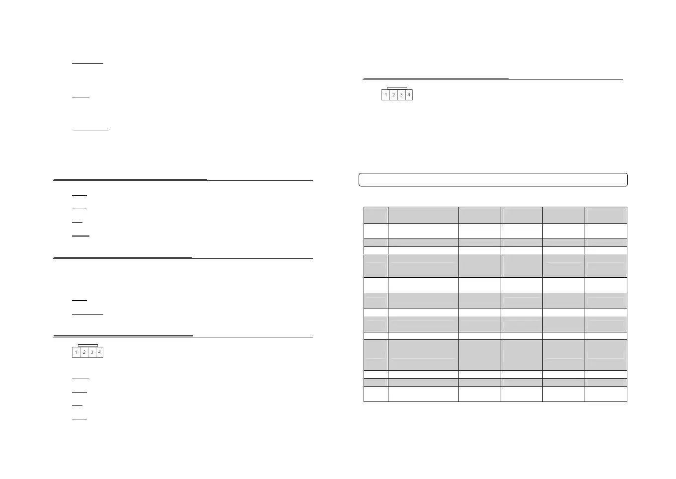
Connector 4 (CN4), 4-Pin (Shock Sensor Port)
Pin 1 Black
- Negative (-) ground.
Pin 2 White
- 2
nd
stage negative (-) input. (Instant trigger)
Pin 3 Red
- 12V positive (+) output.
Pin 4 Yellow
- 1
st
stage negative (-) input. (Warn away)
Connector 5 (CN5), 2-Pin (Pre-wired LED)
Note: Do not mistake for Thermister port.
Pin 1 Black
- L.E.D negative (-) ground.
Pin 2 Black/White
- L.E.D. 3V positive (+) output.
Connector 6 (CN6), 4-Pin (Antenna Cable)
Pin 1 Yellow
- RX input. This wire receives the signal from remote.
Pin 2 White
- TX output. This wire transmits the signal to remote.
Pin 3 Red
– Constant 12V positive (+) output.
Pin 4 Black
– Negative (-) ground.
10
Connector 7 (CN7), 4-Pin (RS232 Data Port)
Pin 1 Constant 12V positive (+) output
Pin 2 Negative (-) ground
Pin 3 RX
Pin 4 TX
Option Programming Tables
IMPORTANT: System must be unlocked before you can set options with the OP500 or remotes.
Feature
Default
Setting- I
Optional
Setting - II
Optional
Setting - III
Optional
Setting - IV
1-01
Lock/Unlock Pulse
Duration
0.8 sec 2.5 sec 0.125 sec 3.5 sec
1-02 Double Pulse Locks Off Unlock Lock Both
1-03 Driver’s Priority Unlock Off On
1-04 Ignition Locks*
Ignition and 30
Sec After
Doors Closed
Drive Lock
Control and
Wire
Off
1-05 Siren Duration 30 Seconds 60 Seconds 120 Seconds
Chirp for 20
Seconds
1-06
Confirmation Chirps
Length
Medium
(30ms)
Short (15ms)
Normal
(60ms)
1-07 Auto Rearm Off 30 Seconds 60 Seconds 5 Minutes
1-08 Passive Arming* Off On
Passive
Without Locks
1-09 Dome Light Delay Off 5 Seconds 45 Seconds Auto
1-10 Valet Mode
Key 5 times,
or Remote
(I+III) while
ignition is on
Key 5 times or
Remote (I+III)
1-11 Open Door Notification On Off
1-12 Factory Alarm Option On Off
1-13
Siren/Horn Mute Control
With Remote
Disabled Enabled
11