EasyManua.ls Logo

Fisher & Paykel DD603-88270 - User Manual

Fisher & Paykel DD603-88270
12 pages
Print Icon
To Next Page IconTo Next Page
Loading...
part number526607 0
08/2006
(page1of 12)
I
®
ishDrawer
TALLATI I T U TI
(NOTE:FORINTEGRATEDPANELPREPARATIONINSTRUCTIONSREFERTOSUPPLIEDSHEET)
DOUBLEDD603 MODELS
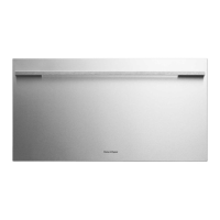
DD603 PREFINISHED(shownleft)
DD603 FLATDOOR(notshown)
DD6031 INTEGRATED(shownright)
SINGLE DS683 MODELS
DS603 PREFINISHED(shownbft}
DS603 FL£ DOOR(not shown}
DS6031 INTEGR£ED(shownright}
NOTE TO THEiNSTALLER
1. Readthese instructions completely and carefully.
2. installation of this DishDrawer® requires basic
mechanical and electrical skills.
3. Be sure to leave these instructions with the Customer.
4. At the completion of the DishDrawer® installation, the
installer must perform Final Check List as per Section 12
of these installation instructions.
5. Remove all packaging materials supplied with the
DishDrawer®.
6. This dishwasher is manufactured for indoor use only.
NOTE TO THECUSTOMER
Keep these Installation Instructions with your User Guide
for future reference. The DishDrawer® must be securely
anchored before # is operated.
Z_WARNING!
Before installing the BishBrawer@ , remove the house fuse or open
the circuitbreaker. Ensureall water connectionsare turned OFF.It is
the responsibilityof the plumber andelectrician to ensure that each
installationcomplieswith all Codesand Regulations.
Important!
These instructions must be followed precisely to ensure correct
venting and operation of the BishBrawer® . In the event of a fault
related to the incorrect installation, the installer will be liable for any
repairs.
important!
The BishBrawer® MUST be installed to allow for future removal
from the enclosure ff service is required.
important!
improperinstallationis not covered under the Warranty.
Important!
if the BishBrawer® is to be relocated from one installation to
another it must be kept upright to avoid damage from water spillage.
Question and Answer IconNeed help?

Do you have a question about the Fisher & Paykel DD603-88270 and is the answer not in the manual?

Summary

Before You Start

Parts Supplied and Tools Needed

Lists components included and tools required for installation.

Installation Preparation Details

Covers electrical, plumbing, power supply, and grounding requirements.

Cavity Preparation Guidelines

Instructions for preparing the installation cavity, including moisture protection.

Step 1: Moving the Product into the Cavity

Mounting Tab Options

Details on using mounting tabs to secure the product to cavity sides.

Optional Flexible Extrusion Use

Guidance on attaching flexible extrusions for specific cavity dimensions.

Step 2: Removing the Tub

Single Models Tub Removal Procedure

Steps for removing the tub from single model DishDrawers.

Double Models Tub Removal Procedure

Steps for removing the tub from the bottom drawer of double models.

Step 3: Adjusting the Feet (Double Models Only)

Foot Adjustment for Cabinetry Height

Adjusting product feet to match cabinetry height and ensure levelness.

Leveling and Stability Check

Ensuring product is level and does not support adjacent cabinetry.

Step 4: Securing the Product

Securing Single Models

Securing the chassis of single models to the cavity using mounting tabs.

Securing Double Models

Attaching top mounting tabs to the underside of the bench for double models.

Step 5: Electrical Connection

Power Outlet Connection

Connecting the DishDrawer to a suitable power outlet, avoiding extension cords.

Permanent Electrical Connection

Instructions for permanent connection via flexible conduit by a certified person.

Step 6: Refitting the Tub

Tub Refitting Procedure

Ensuring hoses are straight, latches forward, placing tub, and closing drawer.

Tub Clip Reset Check

Verifying tub clips are reset, pulling forward if necessary for proper engagement.

Step 7: Connecting the Drain Hose(s)

Drain Hose Joiner Connection

Connecting hoses using a joiner and attaching to the waste tee.

Standpipe Drain Hose Placement

Proper placement of drain hose in standpipe to prevent siphoning.

Drain Hose Support Installation

Attaching support to prevent siphoning and hose kinking.

Step 8: Connecting the Inlet Hose

Water Supply Connection

Connecting the inlet hose to the water supply and checking for leaks.

Alternative Inlet Hose Option

Using a flexible stainless steel hose with a 3/8" adaptor.

Step 9: Measuring the Toe Kick (Double Models Only)

Toe Kick Measurement and Marking

Marking the toe kick position against the tub side for optimal fit.

Step 10: Trimming the Toe Kick (Double Models Only)

Toe Kick Trimming Preparation

Positioning the toe kick on a chopping board before cutting for safety.

Toe Kick Cutting and Finishing

Cutting, bending, finishing edges, and removing rough patches.

Toe Kick Tab Removal

Removing toe kick tabs by snapping them off.

Step 11: Fitting the Toe Kick to the Product (Double Models Only)

Toe Kick Positioning and Attachment

Positioning the toe kick on mounting rails and sliding onto the tub underside.

Toe Kick Flushness and Clearance Check

Checking flushness with cabinetry and minimum floor clearance.

Step 12: Final Checklist

Pre-Operation Checks

Ensuring product is level, secure, connections are made, and power is on.

Wash Program Test

Running a rinse cycle to check operation, drainage, and water supply.

Trouble Shooting Summary

Overview of common issues and initial checks for troubleshooting.

Step 13: Customer Care

Contacting Support

Information on contacting Fisher & Paykel Authorized Service Agent for assistance.

Fisher & Paykel DD603-88270 Specifications

General IconGeneral
BrandFisher & Paykel
ModelDD603-88270
CategoryLCD Drawer
LanguageEnglish

Related product manuals

Fisher & Paykel DD603-88270 - User Manual