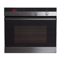
Do you have a question about the Fisher & Paykel OB30SDEPX1 and is the answer not in the manual?
| Series | Series 9 |
|---|---|
| Self-Cleaning | Yes |
| Interior Light | Yes |
| Racks | 2 |
| Rack Positions | 5 |
| Frequency | 60 Hz |
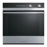
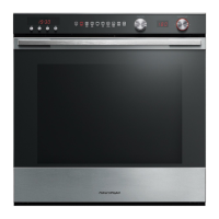
| Color | Stainless Steel |
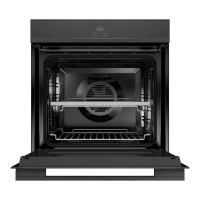
| Type | Built-in |
| Capacity | 3.0 cu. ft. |
| Total Capacity | 3.0 cu. ft. |
| Oven Functions | Bake, Broil, Self Clean |
| Door | Glass |
| Power Supply | 240V |
| Product Dimensions (H x W x D) | 23.5" x 29.875" x 22.5" |
| Width | 29.875" |
Covers electrical safety, ESD protection, good working practices, insulation testing, and sheet metal edge handling.
E.S.D. protection for handling electronic components.
Handheld computer for diagnostics and service information.
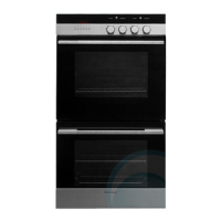
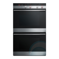
Specifications for the weight of OB30SD and OB30DD models.
Details power consumption for single and double supply voltages.
Physical dimensions of the oven cavity, including width, height, depth, and volume.
Identifies the location of the product serial plate on the oven.
Explanation of the components and meaning within the oven model number.
Details the components and meaning of the oven's serial number.
Describes the operation, modes, voltage, wattage, and frequency of the oven cavity fan.
Details the operation, speed control, voltage, frequency, and wattage of the cooling fan.
Explains the operation, voltage, frequency, and wattage of the active vent fan.
Details the operational modes, voltage, and wattage of the outer broil/grill element.
Details operational modes, voltage, and wattage for the inner broil/grill element.
Describes the location, operational modes, voltage, and wattage of the bake element.
Details operational modes, voltage, and wattage for the fan element.
Lists voltage, max current, max ambient temp, and resistance for the temperature sensor.
Details operation, voltage, and wattage for the oven cavity halogen bulbs.
Specifies voltage for the meat probe and socket assembly.
Explains the operation and voltage of the door lock motor during Self-Clean.
Describes the function and data link of the temperature switch module.
Details the control and display function of the temperature LCD module.
Explains the function of the switch module for setting oven modes.
Details the control and display function of the function LCD module.
Describes the clock module as a micro-controller for oven components and data access.
Describes the PCB that drives lights, fans, elements, motors and monitors sensors.
Lists voltage and frequency details for the power transformer.
Details power rating, resistance, and max ambient temp for the cooling fan resistor.
Identifies the location of thermal limiters (TL) and microtemp limiters (MTL) on single and double ovens.
Describes the MTL's function to detect over-temperature and cut power to transformers.
Details TL 1 & TL 2's function to detect cooling fan failure and cut power to elements.
Explains the relay's function in switching elements, fans, and its energization.
Describes the capacitor's role in providing surge protection for the oven.
Notes the presence of three micro switches within the door lock assembly.
Details the duration, temperatures, heat-up, holding, and cool-down times for the 3-hour cycle.
Details the duration, temperatures, heat-up, holding, and cool-down times for the 5-hour cycle.
Table showing element and fan operation for various oven modes.
Instructions for setting the 12-hour clock and minute timer function.
Explains how to select the desired oven mode using the dial.
Describes how to select the desired oven temperature.
Details the 9 cooking modes, including Warm, Roast, Broil/Grill, and Self Clean.
Explains vent fan operation and cooling fan speed variations during use.
Instructions on how to set, cancel, and use the minute timer function.
Guide to setting automatic and delayed cooking start and stop times.
Procedure for setting the oven to automatically switch off after a specified time.
Enables user customization of control panel settings and displays.
Details how to set and operate the oven in Sabbath mode for religious observances.
Allows changing temperature display between Fahrenheit and Celsius.
Configures audible alerts for timer completion and cooking functions.
Enables switching the clock display between 12-hour and 24-hour formats.
Allows hiding the time display while other functions remain visible.
Sets the display language for oven settings to English, French, Spanish, or DCS.
Resets temperature scale, short alert, time mode, and show clock settings to defaults.
Steps to access Sales Mode and Technician Mode for diagnostics and setup.
Explains how to navigate and use the features within Technician Mode.
Procedure for safely exiting the Technician Mode.
Accessing the log via Smart Tool and details of its sections: Info, Fault, Status, Function, Self-Clean logs.
Adjusts oven temperature settings by +/- 20°F (10°C) in 2°F increments.
Troubleshooting steps for unresponsive oven electrical components, including fuse and transformer checks.
Diagnosing unresponsive buttons, flashing segments, or incorrect display operation.
Troubleshooting jammed, loose, or incorrectly displaying switch modules.
Diagnosing incorrect temperature or oven mode display at the correct switch position.
Troubleshooting steps for faulty temperature or oven mode LCD modules.
Diagnosing 'Doorlock' and 'Probe' messages for the lower cavity in double ovens.
Troubleshooting causes and diagnosis for ovens that undercook food.
Troubleshooting causes and diagnosis for baking that burns on the top of food.
Troubleshooting causes and diagnosis for baking that burns on the bottom of food.
Troubleshooting steps for ovens that appear functional but do not heat.
Diagnosing slow heating or failure to reach preset temperatures in the oven.
Troubleshooting oven light issues: not turning on/off, or bulb replacement.
Diagnosing F1 fault code related to overheating around electronics.
Diagnosing F2 fault code for cavity over-temperature during Self-Clean.
Diagnosing F3 fault code for sensing over 600°F (315°C) during normal cooking.
Procedure for diagnosing and resolving F4 fault code indicating a power module issue.
Diagnosing F5 fault code due to communication error between clock and power modules.
Diagnosing F7 fault code related to a fault with the oven door lock.
Procedure for diagnosing cooling fan faults: not starting or not turning off.
Procedure for diagnosing oven cavity fan faults: not operating or not turning off.
Troubleshooting oven light issues: not turning on/off, or bulb replacement.
Procedure for tracing element faults: run-away or not heating up, includes resistance checks.
Procedure for diagnosing oven temperature sensor faults, including substitution and power module checks.
Procedure for locating tripped thermal limiters and tracing the cause of tripping.
Procedure for diagnosing oven door switch and door lock switch faults.
Procedure to identify the faulty power module in a double oven for F4/F5 fault codes.
Electrical schematic illustrating wiring for a double oven configuration.
Electrical schematic illustrating wiring for a single oven configuration.
Wiring diagram for the temperature protection circuit in double ovens.
Wiring diagram illustrating the neutral circuit connections for oven components.
Wiring diagram for the generic high voltage circuit of the oven.
Wiring diagram for the generic low voltage and lock circuits of the oven.
Wiring diagram illustrating oven lighting and earth circuit connections.
Wiring diagram for the temperature protection circuit in single ovens.
Wiring diagram for the neutral circuit in single oven configurations.
Wiring diagram for the high voltage circuit in single oven configurations.
Wiring diagram for the low voltage and lock circuits in single oven configurations.
Wiring diagram for the lighting and earth circuit in single oven configurations.
Procedure for safely removing the oven from its joinery cavity.
Instructions for accessing components located in the control panel area.
Procedure for accessing components located at the back panel of the oven.
Procedure for accessing electronic components in the service panel area.
Steps for correctly reassembling the oven after servicing.
Procedure for removing and replacing function and temperature switch modules.
Procedure for removing and replacing LCD modules and lenses in the control panel.
Procedure for removing and replacing LCD lenses, ensuring cleanliness.
Procedure for removing and replacing the clock module or control panel buttons.
Procedure for removing and replacing the main power module.
Procedure for removing and replacing the oven's power transformer.
Procedure for replacing thermal limiters and microtemp limiters.
Procedure for removing and replacing the oven temperature sensor.
Procedure for replacing oven lamp glass covers and bulbs.
Procedure for removing and replacing rear oven lamp assemblies.
Procedure for removing and replacing front oven lamp assemblies.
Procedure for removing and replacing the broil/grill element.
Procedure for removing and replacing the fan element.
Procedure for removing and replacing the bake element in single and double ovens.
Procedure for removing and replacing cooling fans in single and double ovens.
Procedure for removing and replacing vent fans in single and double ovens.
Procedure for removing and replacing the oven cavity fan motor and blade.
Procedure for removing and refitting the oven fan shroud.
Procedure for removing and refitting oven runners.
Procedure for safely removing and reinstalling the oven door.
Steps to separate inner and outer door assemblies for servicing.
Procedure for removing and refitting the oven door glass panes.
Procedure for removing and refitting the outer door assembly handle.
Procedure for removing and refitting glass panes from the outer door assembly.
Procedure for removing and refitting oven door hinges and stanchions.
Procedure for removing and replacing the meat probe socket.
Procedure for disengaging, removing, and replacing the oven door lock assembly.
Visual guide showing the location of major oven components.