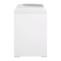
Do you have a question about the Fisher & Paykel WA37T26EW and is the answer not in the manual?
| Brand | Fisher & Paykel |
|---|---|
| Model | WA37T26EW |
| Category | Washer |
| Language | English |
Ensure power is off and use anti-static strap for electronic component servicing.
Maintain tidy work area, isolate water, check for leaks, use edge protection.
Details the function and identification of the Motor Control Module.
Explains the role of the Display Module in user interaction and feedback.
Instructions for setting the machine's size and the consequences of incorrect settings.
How to access and interpret the last recorded fault data.
Procedure to test the drain pump function.
Procedure for testing hot and cold water valves.
Procedure for testing the recirculation valve.
Overview of user-related warnings signaled by LEDs and beeps.
Lists causes for out-of-balance condition.
Table for interpreting diagnostic information using spin speed LEDs.
How to interpret the last user warning from LEDs.
How to interpret detailed fault codes from LEDs.
Details voltage readings for various controller components.
Details resistance readings for various controller components.
Chart for converting wash progress LED states to binary values.
Explains the fault description format and lists primary faults.
Error writing to EEPROM or memory error. Action: Replace Motor Control Module.
Mismatch between display size setting and memory. Action: Reselect size.
Thermistor open circuit or low temperature. Action: Check connection/resistance, replace.
Water level above flood level. Action: Check valves, pump, drain hose.
High current draw from water valve circuit. Action: Check resistance, replace module.
Excessive top-ups during agitate. Action: Check drain hose, leaks, seals.
Water level not changing during drain. Action: Check drain hose, pump, recirculation valve.
Empty water level recorded during agitate. Action: Check pressure tube, replace module.
Pressure tube blocked, kinked, or fallen off. Action: Check tube, replace module.
Basket not engaged when tub is empty. Action: Check clutch, pressure tube.
Memory differences found on power up. Action: Replace Display Module.
Hot and cold valves detected as faulty. Action: Check wiring, valve coils, module.
Water level drop during recirculation. Action: Check valve, solenoid, module.
Motor current reached unrealistically high level. Action: Replace Motor Control Module.
Motor unable to start. Action: Check harness, motor, bearings, module.
Loss of one motor phase. Action: Check harness, stator, module.
Open circuit in lid lock harness or connections. Action: Replace lid lock assembly.
Lid lock mechanism jammed or failed. Action: Check resistance, replace assembly.
Instructions for removing the Motor Control Module.
Steps to clear a blockage in the pump.
Procedure for replacing the shaft and bearings using a tool kit.
Steps for assembling the shaft and bearings.
Troubleshooting steps for a machine with no power.
Common causes and checks for flooding or leaking issues.
