Instruction Manual
D200119X012
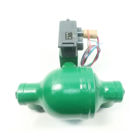
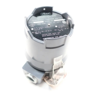
2100 and 2100E Liquid Level Switches
June 2017
3
Table 1. Specifications
Input Signal
Liquid level
Minimum Process Liquid Specific Gravity
0.5 (consult your Emerson sales office
or Local
Business Partner for specific gravity below this value)
Output Signal
2100 Switch: Output equal to supply pressure when
the switch is in the normal
position (flapper against
nozzle). Output reduced to approximately
atmospheric pressure, depending upon size of the
bleed orifice and piping configuration, when the
switch is activated
2100E Switch: Same as supply signal
Supply Signal
2100 Switch: J 2.1 to 4.1 bar (30 to 60 psig), J 4.1
to 6.9 bar (60 to 100 psig), or J 6.9 to 10.3 bar (100
to 150 psig)
2100E Switch: 11 amperes, 1/4 horsepower at
125/250 volts AC; 5 amperes resistive, 3 amperes
inductive at 28 volts DC
Supply Medium (2100 Switch)
Air or Natural Gas
Steady‐State Air Consumption
(1)
(2100 Switch)
Less than 0.03 normal m
3
/hr (1.0 scfh) for all supply
pressures when the liquid level is 25.4 mm (1 inch)
below the normal switch position (flapper against
nozzle) for high‐level switching or 25.4 mm (1 inch)
above the normal switch position for low‐level
switching
Maximum Working Pressure
(2)
J153 bar (2220 psig) WOG
(3)
except J24 bar
(350 psig) WOG is the maximum working pressure for
sight window construction
Operative Temperature Range
(2)
2100 Switch: -29 to 204_C (-20 to 400_F)
2100E Switch: -29 to 82_C (-20 to 180_F)
Displacer Diameter
102 mm (4 inches)
Process Connection Size
153 Bar (2220 psig) WOG
(3)
: J1 NPT internal
JDN 50 (NPS 2) Schedule 80 buttwelding ends, or
JDN 50 (NPS 2) Schedule 160 buttwelding ends
2100 Switch Supply Pressure Connection Size
1/4 NPT internal
2100E Switch Electrical Connection Size
1/2 NPT external
Hazardous Area Classification for 2100 Switch
The 2100 pneumatic switch complies with the
requirements of ATEX Group II Category 2 Gas and
Dust
Hazardous Area Classification for 2100E Switch
CSA, FM, ATEX, IECEx, UL, CUTR
Refer to Hazardous Area Classifications and Special
Instructions for “Safe Use” and Installations in
Hazardous Location on page 4.
Contact your Emerson sales office or Local Business
Partner if additional information is required.
Shipping Weight
17.2 kg (38 pounds)
Declaration of SEP
Fisher Controls International LLC declares this
product to be in compliance with Article 3 paragraph
4 of the PED Directive 2014/68/EU. It was designed
and manufactured in accordance with Sound
Engineering Practice (SEP) and cannot bear the CE
marking related to PED compliance.
However, the product may bear the CE marking to
indicate compliance with other applicable European
Community Directives.
NOTE: Specialized instrument terms are defined in ISA Standard 51.1 - Process Instrument Terminology.
1. Normal m
3
/hr—normal cubic meters per hour (0_C and 1.01325 bar, absolute); scfh—standard cubic feet per hour (60_F and 14.7 psia)
2. Pressure and temperature limits in this document and any applicable standards or code limitations should not be exceeded.
3. Water, Oil, Gas maximum working pressure rating. Corresponds to Cold Working Pressure: the maximum pressure rating allowed under normal ambient temperature conditions, which are
usually understood to be -29_C to 38_C (-20_F to 100_F). Refer to MSS SP‐25.