D200106X012
Fisher Controls International, Inc. 1987, 1996; All Rights Reserved
Fisher, Fisher-Rosemount, and Managing The Process Better are marks owned
by Fisher Controls International, Inc. or Fisher-Rosemount Systems, Inc.
All other marks are the property of their respective owners.
Type
3
0
4 a
n
d 3
04
L E
lectrica
l
Positio
n S
witch
Contents
Introduction
1.
. . . . . . . . . . . . . . . . . . . . . . . . . . . . . .
Scope of Manual 1.
. . . . . . . . . . . . . . . . . . . . . . . . . . .
Description 1
. . . . . . . . . . . . . . . . . . . . . . . . . . . . . . . . .
Specifications 1
. . . . . . . . . . . . . . . . . . . . . . . . . . . . . .
Installation
3
. . . . . . . . . . . . . . . . . . . . . . . . . . . . . . . .
Mounting the Position Switch on the Actuator 3.
. .
Mounting the Position Switch on
Other Devices 4.
. . . . . . . . . . . . . . . . . . . . . . . . . . . . .
Electrical Connections 5.
. . . . . . . . . . . . . . . . . . . . . .
Adjustment
6
. . . . . . . . . . . . . . . . . . . . . . . . . . . . . . .
Principle of Operation
6.
. . . . . . . . . . . . . . . . . .
Maintenance
7
. . . . . . . . . . . . . . . . . . . . . . . . . . . . . .
Parts Ordering
8.
. . . . . . . . . . . . . . . . . . . . . . . . . . .
Parts List
8.
. . . . . . . . . . . . . . . . . . . . . . . . . . . . . . . .
Position Switch Common Parts 8.
. . . . . . . . . . . . . .
Terminal Strip Assembly 8.
. . . . . . . . . . . . . . . . . . . .
Position Switch Mounting Parts 8.
. . . . . . . . . . . . . .
Additional Actuator Parts for Field Mounting 22.
.
Introduction
Scope of Manual
This instruction manual provides installation, adjust-
ment, maintenance, and parts ordering information for
the Type 304 and 304L electrical position switches.
This manual also provides ordering information for the
hardware used to mount the switches on Fisher actua-
tors.
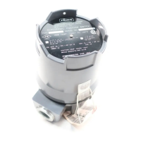
Figure 1. Type 304 Electrical Position Switch with
Cover Removed
W5939 / IL
Only personnel qualified through training or experience
should install, operate, and maintain these position
switches. If you have any questions concerning these
instructions, contact your Fisher Controls sales office
or sales representative before proceeding.
Description
The Type 304 and 304L switches are normally
mounted on a control valve actuator to operate
alarms, signal lights, relays, solenoid valves, or other
equipment when valve travel reaches predetermined
points.
The Type 304 position switch (see figure 1) is for ap-
plications that require only one or two switches. The
Type 304L position switch is for applications that re-
quire three or more switches with a maximum of six
switches (see figure 3). The individual switches can be
adjusted to operate at any point of travel within the 90
degrees of cam rod rotation.
Specifications
Specifications for the Type 304 and 304L electrical
position switches are listed in table 1.
Instruction Manual
Form 2007
October 1996
Type 304 & 304L