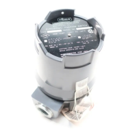
Type 304 & 304L
8
Parts Ordering
Whenever corresponding with the Fisher sales office
or sales representative about this equipment, always
mention the position switch serial number. When or-
dering replacement parts, refer to the 11-character
part number of each required part as found in the fol-
lowing parts list.
Parts
List
Position Switch Common Parts (figure 6)
Key Description Part Number
1 Base assembly, aluminum 11A8584X012
2 Cover assembly, aluminum
2 switch unit 19A8070X012
6 switch unit 29A8069X012
4 Switch post, pl steel (3 req’d)
2 switch unit 1N251024502
6 switch unit 1N251124502
5* Switch (1 to 6 req’d) 1P123299012
6 Switch insulator (2 to 7 req’d) 1N251606992
7 Spring washer, pl steel (2 req’d per switch) 1P271028992
8 Lockwasher, pl steel (3 req’d) 1H267128982
9 End plate, pl steel 1N251728992
10 Hex nut, pl steel (4 req’d) 1A330328982
11 Cam rod, stainless steel
2 switch unit 1U868135032
6 switch unit 1N807535032
12 Cam, stainless steel (1 req’d per switch) 1P129636032
13 Hex Nut, pl steel (1 req’d per switch) 1A946324122
14 Gear, pl steel (1 req’d per switch) 1P270924592
15 Washer, pl steel (1 req’d per switch) 10B2660X012
16 E-ring, pl steel (2 req’d) 1H153828982
17 Washer, pl steel (2 req’d) 1C332928982
18 Switch spacer, pl steel
2 switch unit
1 switch (2 req’d) 1N252924102
2 switches (none req’d) - - -
6 switch unit
1 switch (10 req’d) 1N252924102
2 switches (8 req’d) 1N252924102
3 switches (6 req’d) 1N252924102
4 switches (4 req’d) 1N252924102
5 switches (2 req’d) 1N252924102
6 switches (none req’d) - - -
21 Nameplate, aluminum
for switch with no approval 14A2115X0A2
22 Machine screw, pl steel 1P426928982
23 Spacer plate, pl steel (not shown)
(none required with terminal strip) 1P129525022
24* O-Ring, nitrile 1H862106992
25 Seal retainer, stainless steel 1V5834X0012
26* O-ring, nitrile 1C853806992
107
Wire retainer
16A2821X012
115 Lubricant, Lubriplate Mag-1 (not furnished with switch)
116 Adhesive, Loctite, #609 (not furnished with switch)
Key Description Part Number
Terminal Strip Assembly (figure 6)
30 Screw, pl steel
2 switch unit
1 switch (4 req’d) 1D677628992
2 switches (8 req’d) 1D677628992
6 switch unit (8 req’d) 1D677628992
31 Bracket, pl steel
2 switch unit 24A2116X012
6 switch unit 24A2109X012
32 Terminal strip
2 switch unit
1 switch (1 req’d) 1J304299012
2 switches (2 req’d) 1J304299012
6 switch unit (2 req’d) 1H767499012
33 Marker Strip 1
2 switch unit 1U872106992
6 switch unit 1U830906992
34 Marker Strip 2
2 switch unit
1 switch (none req’d) - - -
2 switches (1 req’d) 1U872206992
6 switch unit (1 req’d) 1U830806992
35 Red wire assembly
(1 req’d per switch) (not shown) 14A0758X012
36 Blue wire assembly
(1 req’d per switch) (not shown) 14A0759X012
37 Black wire assembly
(1 req’d per switch) (not shown) 14A0760X012
Position Switch Mounting Parts
Note
In this section, the letters ‘‘MO’’ (means manual opera-
tor) following a type number or size indicate that the
actuator has a manual handwheel.
Type 329 Actuators
See section covering Type 329, 1051, 1052,
1061, and 1069 actuators below.
Type 350 and 350MO Actuators (figure 7)
40 Mounting plate, assembly, steel
Type 350 and 350MO
2-13/16 (71 mm) boss 10A8524X012
3-9/16 (90 mm) boss 12A2348X012
43 Machine screw, pl steel (4 req’d) 1C582428982
44 Lockwasher, pl steel (4 req’d) 1C225628982
45 Cap screw, pl steel (2 req’d)
Type 350
2-13/16 (71 mm) and 3-9/16 (90 mm) boss 1A352524052
Type 350MO
2-13/16 (71 mm) boss 1A352524052
3-9/16 (90 mm) boss 1C870224052
46 Lockwasher, pl steel 1C225728982
47 Spacer, pl steel
Type 350
2-13/16 in. (71 mm) boss 1N254324102
3-9/16 in (90 mm) boss (none req’d) - - -
Type 350MO
2-13/16 in. (71 mm) boss 1N254324102
3-9/16 (90 mm) boss 1N466124102
*Recommended spare parts

 Loading...