Type 304 & 304L
3
Table 4. Assembly Drawing References
ACTUATOR TYPE
(1)
SIZE
FIGURE
NUMBER
329
350 Series
470
470
470
470 with
covered yoke
All
All
30
40 through 68
80 through 100
80
17
7
8
7
14
8
478
478-16
478-16
513 and 513R
585 and 585R
585C and 585CR
657 and 667
657 and 667 with
covered yoke
40 through 68
60 and 68
80 and 100
20 and 32
25, 50, and 100
25 and 50
30 and 34
40 through 70
7
9
14
10
11
12
13 and 15
13
657 and 667
657 and 667
1051, 1052, and 1061
1051 and 1052
1052
40 through 70
80 and 87
30, 40, 60, 68, and 70
33
20
7 and 15
7, 14, & 15
16
18
19
1061 and 1069
1066 and 1066SR
1076
1077
1078
1250 and 1250R
Additional field
mounting parts
80 and 100
20, 27, and 75
1, 2, and 3
0-, 2-, 6-, 7-, and 9-KE
A, AA, and AAA
225, 450, and 675
– – –
17
20
21
22
23
24
25
1. Contact your Fisher Controls sales office or sales representative for information for
mounting on actuator types and sizes not listed.
Installation
When Type 304 and 304L switches are ordered with
an actuator, the factory mounts the position switch and
adjusts the cams for the travel specified on the order.
When installation is complete, the cam adjustments
should be checked as described in the adjustment pro-
cedures.
If the position switch has been ordered separately, or
removed for maintenance, refer to the appropriate pro-
cedure for mounting.
Mounting the Position Switch on the
Actuator
To mount a Type 304 or 304L position switch on a
Fisher Controls actuator in the field, see the additional
actuator parts for field mounting section of the parts
list. These additional parts, plus those parts listed in
the position switch mounting parts section, are re-
quired for some actuators.
Refer to the appropriate actuator instruction manual
for procedures to disassemble and assemble actuator-
to-valve connections if required.
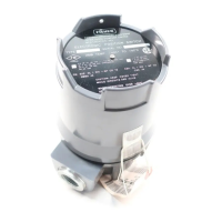
Figure 2. T
ypical Nameplate with Hazardous Area
Classification Information
INFORMATION IN THIS PORTION OF THE
NAMEPLATE IDENTIFIES THE HAZARDOUS
AREA CLASSIFICATION AND APPROVALS
FOR THE PRODUCT SPECIFIED ON THE
EQUIPMENT ORDER.
11A4723–K SHT 1 / IL
WARNING
Avoid personal injury from sudden re-
lease of process pressure. Before disas-
sembly:
D Disconnect any operating lines pro-
viding air pressure, electric power, or a
control
signal to the actuator
. Be sure the
actuator cannot suddenly open or close
the valve.
D Use bypass valves or completely
shut off the process to isolate the valve
from process pressure. Relieve process
pressure from both sides of the valve.
Drain the process media from both sides
of the valve.
D Use lock-out procedures to be sure
that the above measures stay in effect
while you work on the equipment.
D Vent the power actuator loading
pressure and relieve any actuator spring
precompression.
D For 304 switches in intrinsically
safe
areas, current monitoring during opera-