Type 304 & 304L
5
NOTES:
1. THE CIRCUIT DIAGRAM SHOWN WITH EACH CAM AND ROLLER IS THE INTERNAL CONNECTIONS WITHIN THE SWITCH. THE CIRCUIT IS SHOWN
SCHEMATICALLY, AND DOES NOT REPRESENT THE ACTUAL MECHANICAL DESIGN.
2. SWITCH TERMINAL DESIGNATIONS:
COM—STANDS FOR COMMON. ITIS THE COMMON CONNECTION POINT BETWEEN THE NC AND NO TERMINALS.
NC—STANDS FOR NORMALLY CLOSED CONTACTS. CONNECTION IS CLOSED BETWEEN THIS TERMINAL AND THE COM TERMINAL WHEN SWITCH IS
IN THE NORMAL CONDITION. CONNECTION IS OPEN (NO CONTACT) WHEN SWITCH IS ACTUATED
NO—STANDS FOR NORMALY OPEN CONTACTS. CONNECTION IS OPEN (NO CONTACT) BETWEEN THIS TERMINAL AND THE COM TERMINAL WHEN
SWITCH IS IN THE NORMAL CONDITION. CONNECTION IS CLOSED WHEN SWITCH IS ACTUATED.
3. TRIP POINT IS THE POINT AT WHICH THE SWITCH CHANGES FROM THE NORMAL CONDITION TO THE ACTUATED CONDITION, OR VICE VERSA.
SWITCH
HOUSING
TRIP POINT
NCNO COM
Figure
4. Standard Switching Conditions
Maximum
Clockwise
Shaft Rotation
Intermediate
Shaft Position
Maximum
Counterclockwise
Shaft Rotation
Switch Set
to change
State at
maximum
counter-
clockwise
shaft
rotation
Switch
Set to
change
state at
maximum
clockwise
shaft
rotation
MARKED COM
MARKED NC
MARKED NO
TYPICAL SWITCH HOUSING
(2)
CAM ROD
LINKAGE
CAM
ROLLER AND ARM
SWITCH CONDITION IN RELATION TO RIP POINT
(3)
NCNO COM NCNO COM NCNO COM
NCNO COM
NCNO COM NCNO COM
NCNO COM
A6894 / IL
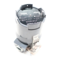
Electrical Connections
Make the required electrical connections through the
conduit connection in the base (figure 3). Use a suit-
able conduit connector for hazardous locations. If the
unit is equipped with an optional terminal strip, make
connections to the strip. If the unit does not have a
terminal strip, make connections directly to the individ-
ual switches. A ground terminal connection is provided
by the green wire retainer and screw in the base.
CAUTION
For explosion-proof applications, install
a suitable conduit seal no more than 18
inches (460 mm) from the position
switch. Personal injury or property dam-
age may result if seal is not installed.
To obtain a normally-closed circuit (the circuit for an
individual switch is closed until the switch is actuated),
wire to the C (common) and the NC (normally-closed)
terminals. To obtain a normally-open circuit (the circuit
for an individual switch is open until the switch is actu-
ated), wire to the C (common) and the NO (normally-
open) terminals.
Unless specified otherwise on the order, switch 1 (the
switch closest to the base) changes state (changes
from mornal to actuated) at the valve-closed position.
Unless otherwise specified, the switch farthest from
the base changes state (changes from normal to actu-
ated) at the valve fully open position. Refer to figure 4
for standard switching conditions.