Type 304 & 304L
7
As the actuator stem travels downward (for sliding-
stem valves) or as the valve shaft rotates counter-
clockwise (for rotary valves), the switch roller rides up
on the small radius of the cam lobe, actuates the
switch, and rests on the lobe during the remainder of
the travel. The normal or un-actuated position of the
switch is with the roller positioned over, but not touch-
ing, the 3/8-inch (9.5 mm) radius of the cam as shown
in figure 5.
Maintenance
WARNING
Avoid personal injury from sudden re-
lease of process pressure. Before disas-
sembly:
D Disconnect any operating lines pro-
viding air pressure, electric power, or a
control
signal to the actuator
. Be sure the
actuator cannot suddenly open or close
the valve.
D Use bypass valves or completely
shut off the process to isolate the valve
from process pressure. Relieve process
pressure from both sides of the valve.
Drain the process media from both sides
of the valve.
D Use lock-out procedures to be sure
that the above measures stay in effect
while you work on the equipment.
D Vent the power actuator loading
pressure and relieve any actuator spring
precompression.
WARNING
For 304 switches in intrinsically safe
areas, current monitoring during must
be with an approved meter for hazard-
ous areas in order to avoid personal in-
jury or property damage caused by an
explosion or fire.
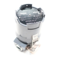
Refer to figure 6 for key number locations.
WARNING
On an explosion-proof instrument, re-
move electrical power before removing
the instrument cover in a hazardous
area. Personal injury or property dam-
age may result from fire and explosion if
power is applied to the instrument with
the cover removed in a hazardous area.
To replace switches, open the circuits between the
switch and power source, and unscrew the cover (key
2). Record the wire connections to the defective switch
or switches. Remove the hex nuts, lockwashers, and
end plate (keys 10, 8, and 9). Remove any spacers
(key 18). Disconnect the wires from the switches, and
slide the switches off the switch posts (key 4). After
replacing switches, attach the wires as recorded. Ad-
just the switch cams as described in the Adjustment
section.
To minimize the possibility of moisture entering the
switch, inspect and replace the O-rings (keys 24 and
26) as necessary. To replace the small O-ring (key
26), first remove the cover (key 2). Then remove the
E-ring (key 16). Remove the hex nuts, lockwasher,
and end plate (keys 8, 9, 10, and 17) from the switch
post (key 4). Carefully remove the cam rod (key 11)
from the base (key 1). Then, remove the small O-ring
(key 26). Apply an appropriate lubricant to the O-ring.
When reassembling, lubricate the portion of the cam
rod that contacts the bearing in the base with a good
quality grease. Follow this procedure in reverse to re-
place the O-ring and cam rod.
The large O-ring (key 24) is held in place by the cover
(key 2). With the cover removed, slide the O-ring off
the base (key 1), inspect and replace the O-ring (key
24) as necessary. Apply an appropriate lubricant to the
O-ring, and slide the O-ring into position on the base.
Apply an appropriate lubricant or anti-seize compound
to the threads on the base, and replace the cover.
CAUTION
The presence of Fisher Controls person-
nel and also approval agency personnel
may be required if you service (other
than normal, routine maintenance, such
as calibration) or replace components in
an instrument that carries a third-party
approval. When you replace compo-
nents, use only components specified
by the factory. Substitution with other
components may void the third-party
approval. Always use proper compo-
nent replacement techniques. Poor
quality repairs can impair the safety fea-
tures of the device.
 Loading...