Type 304 & 304L
4
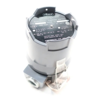
Figure 3. Location of Parts for T
ype 304L Position Switch
SWITCH
ROLLER
ADJUSTMENT
ROLLER
GEARED
NUT
CAM
CAM EAR
GROUND
TERMINAL
BASE
W5940 / IL
tion must be with an approved meter for
hazardous
areas in order
to avoid person
-
al injury or property damage caused by an
explosion or fire.
WARNING
Refer to the appropriate actuator
instruction manual before removing the
actuator-to-valve connection. Personal
injury or property damage may result
from sudden release of preloaded
spring force.
Generally, the position switch is attached to the
mounting plate with machine screws, and the mount-
ing plate is installed on the actuator. Then, the con-
necting linkage or coupling between the actuator and
position switch is installed.
Refer to table 4 for references to the assembly draw-
ing figures that show typical installations of the posi-
tion switch.
After mechanically connecting the position switch to
the actuator, refer to the electrical connections and
operating information sections to place the position
switch in operation.
Mounting the Position Switch on Other
Devices
For other applications of the position switch, provide
suitable mounting hardware. If the motion of the moni-
tored device is linear, provide a lever arm to convert
the linear motion to rotary motion. The lever arm
should be limited to 90 degrees of rotation from the
point at which the first switch actuates. This ensures
that the first switch remains actuated until the input
motion is reversed.
If the motion of the monitored device is rotary, the
switch can be coupled directly to the device if the
rotary motion does not exceed 90 degrees from the
point at which the switch first actuates. If the rotary
motion of the device is greater than 90 degrees after
the first switch actuates, provide a gear and/or lever
arm to reduce the rotation to 90 degrees or less.
After connecting the switch to the device, refer to the
electrical connections and operating information proce-
dures to place the position switch in operation.