Type 304 & 304L
6
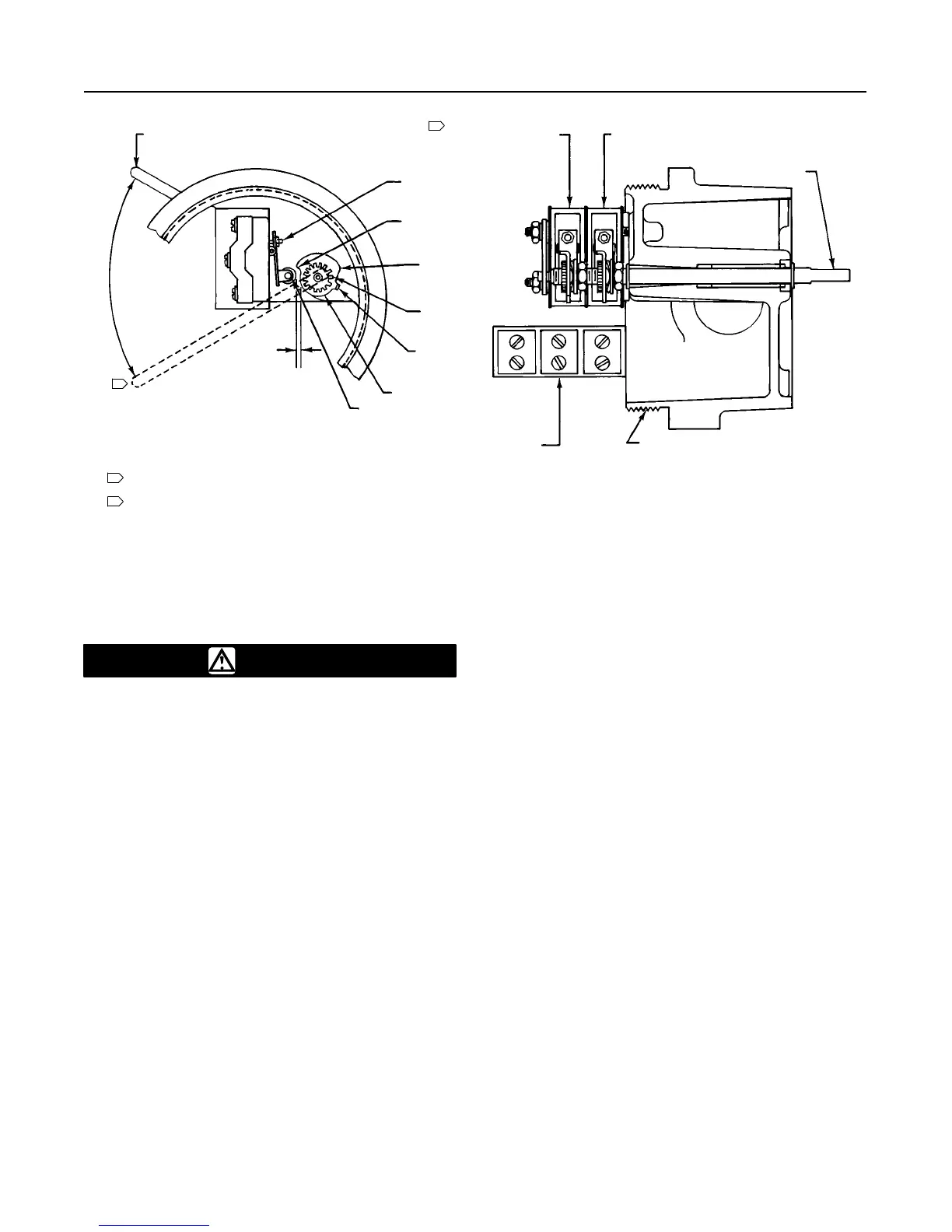
NOTES:
SWITCHES ACTUATE AS ACTUATOR STEM TRAVELS
DOWN OR AS ROTARY VALVE SHAFT ROTATES COUNTERCLOCKWISE.
SWITCH FARTHEST FROM BASE ACTUATES AT FULLY
OPEN VALVE POSITION.
Figure 5. Cam and Switch Details
42A0105–D
B1818–3 / IL
ACTUATOR STEM
UP
OPTIONAL SWITCHES
ARE SET AS REQUIRED
SWITCH 1 ACTUATES AT VALVE
CLOSED POSITION
CAM ROD
BASE
TERMINAL STRIPS
ARE OPTIONAL
ROLLER
ADJUSTMENT SCREW
SMALL RADIUS
CAM HEEL
GEARED NUT
CAM EAR
3/8–INCH (9.5 mm) RADIUS
ROLLER
1/16 INCH
(1.6 mm)
ACTUATOR STEM
DOWN
2
1
1
2
Adjustment
WARNING
On an explosion-proof instrument, re-
move electrical power before removing
the instrument cover in a hazardous
area. Personal injury or property dam-
age may result from fire and explosion if
power is applied to the instrument with
the cover removed in a hazardous area.
1. Position the valve or monitored device at the point
of travel where actuation of a particular switch is de-
sired.
2. Open the circuits between the switch and power
supply, and remove the switch cover.
3. Refer to figure 3. Use a light or ohmmeter to indi-
cate switch actuation. Insert a screwdriver into the
geared nut of the appropriate switch and pry against
the cam ear. Rotate the cam until its small radius (see
figure 5) contacts the lever arm roller and actuates the
switch. Tension provided by a spring washer holds the
cam in place.
4. Always adjust the cams so that the small radius of
the cam actuates the switches. This minimizes the
differential travel (dead band) required to make and
then break the circuit. The switch should not actuate
on the heel of the cam; this increases the dead band.
5. To ensure switching at the open and closed valve
positions, set the switch to actuate approximately
1/32-inch (0.8 mm) before the valve reaches these
positions.
6. The lever arm roller is preset at the factory approxi-
mately 1/16-inch (1.5 mm) from the 3/8-inch (9.5 mm)
radius of the cam, as shown in figure 5. Adjust this
dimension by turning the adjustment screw on the
switch lever arm. Use the adjustment screw only to
position the lever arm in relation to the cam; do not
use the screw to adjust the point at which the switch
actuates.
7. Replace the cover (key 2).
Principle of Operation
When used with sliding-stem valves, the operating arm
(key 49, figure 7) converts linear valve travel to rotary
motion of the cam rod.
When used with rotary shaft valves, the coupler (key
105, figure 16) links the position switch and the rotary
actuator directly and rotates the cam rod.
As the cam rod rotates, cams mounted on the rod
contact the switch rollers and actuate the switches,
which opens or closes individual switch circuits.