Instruction Manual
D200119X012
2100 and 2100E Liquid Level Switches
June 2017
6
Installation Procedures
The installation procedures include those common to both the 2100 pneumatic and 2100E electric liquid level
switches and additional ones for each switch.
Common Procedures for Either Switch
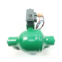
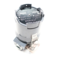
The horizontal line forged on the displacer cage indicates the approximate switching point (figures 1 and 2). When you
mount the 2100 or 2100E switch, position it so that the horizontal line corresponds to the horizontal level at which
switching is desired.
Before you install the 2100 or 2100E switch, remove the plastic plugs from the process connections. One of these
plugs retains a paper tube that protects the displacer and torque tube during handling and shipping. This paper tube
must also be removed.
There are two process connections; one at the top and one at the bottom of the cage. To mount the switch, connect
the appropriate top and bottom process connections to the vessel using the required size pipe. The pipe must be
capable of supporting the assembly and of withstanding the pressure involved. Use accepted piping and welding
practices when making connections. Install isolating valves between the vessel and cage. Plugs are furnished for the
unused process connections. However, one of the plugs can be removed, and a bleed valve or drain can be installed in
one of the unused connections.
Additional Procedures for 2100 Switch
If using natural gas as the pneumatic supply medium, natural gas will be used in the pressure connections of the unit
to any connected equipment. The unit will vent natural gas into the surrounding atmosphere, unless it is remote
vented.
WARNING
Personal injury or property damage may occur from an uncontrolled process if the 2100 switch supply medium is not clean,
dry air or noncorrosive gas. If clean, dry air, or noncorrosive gas is not used, the switch may become inoperative and allow
the level in a process vessel to exceed safe limits. Install a 40 micrometer filter and suitable equipment to dry the supply
medium and establish a maintenance cycle to check the filter and equipment.
If the existing supply medium is corrosive, make sure the tubing and instrument components that contact the corrosive
medium are suitable corrosion‐resistant materials, or use a noncorrosive medium.
WARNING
Personal injury or property damage may result from fire or explosion if natural gas is used as the supply medium and
preventative measures are not taken. Preventative measures may include: Remote venting, re‐evaluating the hazardous
area classification, ensuring adequate ventilation, and the removal of any ignition sources.
CAUTION
Do not use sealing tape on pneumatic connections. This instrument contains small passages that may become obstructed
by detached sealing tape. Thread sealant paste should be used to seal and lubricate pneumatic threaded connections.