Instruction Manual
D100348X012
2625, 2625SST, and 2625NS Volume Booster
May 2017
6
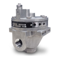
Figure 3. Typical Installations
VOLUME BOOSTER
B2372‐1
VOLUME BOOSTER
VOLUME BOOSTER
POSITIONER OUTPUT
POSITIONER
POSITIONER OUTPUT
(TOP CYL)
SIGNAL
SUPPLY
POSITIONER
POSITIONER OUTPUT
(BOTTOM CYL)
PIPE TEE
PIPE BUSHING
BODY
BODY PROTECTOR
INPUT SIGNAL
PIPE TEE
PIPE BUSHING
BODY
BODY PROTECTOR
ACTUATOR
ACTUATOR
OPTIONAL
DIAGNOSTIC
CONNECTION
OPTIONAL
DIAGNOSTIC
CONNECTION
SUPPLY
67D, 67DR, OR MR95H
PIPE NIPPLE
PIPE NIPPLE
WITH A PISTON ACTUATOR
WITH A DIAPHRAGM ACTUATOR
67D, 67DR, OR MR95H
Diagnostic Connections
To support diagnostic testing of valve/actuator/positioner packages, install connectors and hardware between the
2625, 2625SST, or 2625NS volume booster and the actuator. Typical connector installations are shown in figure 3.
The hardware used includes a 3/4 NPT pipe nipple, pipe tee, and pipe bushings with an 1/8 NPT pipe bushing for the
connector. The connector consists of an 1/8 NPT body and body protector.
See separate instructions for diagnostic connections to the positioner.
 Loading...