Instruction Manual
D100348X012
2625, 2625SST, and 2625NS Volume Booster
May 2017
9
your finger. If the spring seat (key 9) does not move freely in the spring case assembly (key 3), remove the spring
seat (key 9), and apply lubricant (key 23). Reinstall the spring seat (key 9) in the spring case assembly (key 3).
CAUTION
To avoid damage to the diaphragms, do not overtighten the screws.
5. Replace the six cap screws (key 15) and tighten them in a crisscross manner.
Valve Assembly Replacement
CAUTION
The distance between the exhaust port seat line on the upper valve (key 7C) and the supply port seat line on the lower valve
and stem (key 7B) is critical to ensure the deadband requirements of the volume booster. This distance is set at the factory
and is not field adjustable. If replacement is necessary, use the proper factory authorized repair kit listed in the parts
section below. All components of the repair kits are factory set and tested and are not field adjustable.
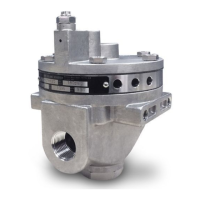
For key numbers refer to figure 4.
Figure 4. Volume Booster Assembly Drawing
DV4286‐B
 Loading...