EasyManuals Logo

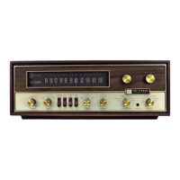
Fisher 700-T User Manual

Fisher 700-T
16 pages
To Next Page IconTo Next Page
To Previous Page IconTo Previous Page
Page #10 background imageLoading...
Page #10 background image
|
1489-3
DRIVER
|
PARTS
DESCRIPTION
LIST
CAPACITORS
Symbol
Description
Part
No.
C851,
852
Electrolytic,
25uF,
15V
C508637-6
C853
Electrolytic,
200uF,
35V
C50483-7
RESISTORS
Deposited
carbonin
ohms,
5%
tolerance,
4
watt,
unless
otherwise
noted,
K=Kilohms,
M=Megohms.
Symbol
Description
Part
No.
R851
15K
R50DC1534
R852
8.2K
R500C8225
R853
Composition,
3.9K
RC20BF3925
R854
56K
R50DC563J
R855
.
220
R50DC221J
R856
Composition,
82°
RC20BF8205
R857
Por.,
300,
20%,
Center
Voltage
Adjust
R50B499-1
R858
Pot.,
300,
20%,
Output
Bios
Adjust
R50B499-1
R859
2.2K
R500C2225
R860
.
3.3K
R50DC332J
R861
Composition,
82
RC206F8205
R862
56K
R500C563J
R863
Composition,
120
RC20BFI215
R864
Composition,
82
RC20BF820J
MISCELLANEOUS
Symbol
Description
Part
No,
CR85)
Diode,
Silicon
S$1D50894
.
CRB52,853
Diode,
Zener,
6.8V,
5%,
1W
ZR50921-2
CR854,855
Diode,
Silicon
$1D50894
Q851,
852
Transistor,
TRIO005S
°
TR1005
Q853
Transistor,
TR1004
TR1004
POWER
AMPLIFIER
CENTER
VOLTAGE
ADJUSTMENT
@
Connect
two
10K,
1%
resistors
in
series
across
capacitor
C19
(2500uF).
Connect
the
common
lead
of
a
DC
VTYM
to
the
junction
of
the
two
resistors,
@
Connect
OC
VTVM
to
the
junction
of
resistors
R37
and
R39.
Adjust
Center
Voltage
Adjust
Pot,
R857
on
left
channel
driver
board
for
meter
reading
of
0
+0.5
VDC.
@
Connect
DC
VTVYM
to
the
junction
of
resistors
R38
and
R40,
Adjust
Center
Voltage
Adjust
Pot.
R857
on
right
channel
driver
board
for
meter
reading
of
0
+0.5
YDC.
@
Disconnect
10K
resistors.
POWER
AMPLIFIER
IDLING
CURRENT
ADJUSTMENT
NOTE:
This
adjustment
is
to
be
performed
only
after
com-
pleting
Center
Voltege
Adjustment.
@
Connect
OC
VTVM
across
resistor
R37,
Adjust
nat
Bias
Adjust
Pot.
R858
on
Jeft
channel
driver
board
for
meter
read-
ing
of
40
#10mV
OC.
@
Connect
DC
VTVM
across
resistor
R38,
Adjust
Output
Bias
Adjust
Pot.
R858
on
right
chonnel
driver
board
for
meter
read
ing
of
40
t10mV
OC.
ee
ty
eat
i
en
Se
Oe
|
820
TRIOOS
TRIOO4
>
3
a®o
°
°
Ee
¢
—E
¢
Q4
(Q2)
+63V
CENTER
VOLTAGE
+31.5V
1200
Qssi
TRIOOS
“CENTER
:
,
VOLTAGE
ADJUST
>
C)
|
|
AW2521
TO
FEEDBACK
P1489-3
AS
BOARD
VIEWED
FROM
COMPONENT
SIDE
TT
CENTER
ea
na
[
NOLTAGE
wt
Raéi
|
Adv.
N
foray
a
|
/
\
(e
fey
oesz
-
ez
[ex
TO
EMITTER
|
as
(
als
\
a
ae
ya
NT
Ki
OF
Q4(Q2)
er
ee
,
PSH
gthte”
«GS
tes
TO
BASE
OF
perl
©
;
ora
:
Q4(Q2)
poe
oti
POWER
DC
CENTER
‘gilts
ed
TO
;
aye
STABISTOR
FEEDBACK
.
Ao:
lee
.
+30v
SN
_@
*
+1
oes
*
Tee
TO
STABISTOR
:
Tae
ne
ale
Ta
lag
TO
COLLECTOR
6P
7
.
CRASS
ir
—@
eer
arenes
ea
oe
OF
Q3(Q1)
7
ee
Ga
AS
4k
@
TO
EMITTER
INPUT
——-@)
:
a
R63:
‘|
OF
Q3(QI)
2
:
—y
18A
TO
BASE
Raga
O
OF Q3
(QI)
INS
388
*
FOR
VALUE
SEE
PARTS
LIST
P1489
-2
Pi4a9-3
%*
SEE
SCHEMATIC
i
s3-semiost(-t)

Questions and Answers:

Question and Answer IconNeed help?

Do you have a question about the Fisher 700-T and is the answer not in the manual?

Fisher 700-T Specifications

General IconGeneral
BrandFisher
Model700-T
CategoryReceiver
LanguageEnglish

Related product manuals