C1 Controllers and Transmitters
Instruction Manual
September 2009
37
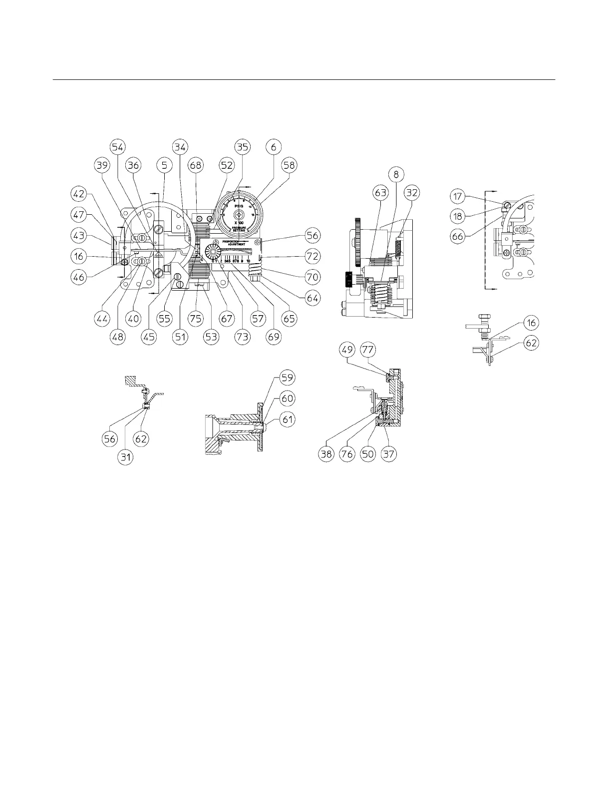
BOURDON TUBE TRAVEL
STOP SUBASSEMBLY
NOTE:
KEYS 33 AND 74 ARE NOT SHOWN
A
A
B
A
A
C
SECTION A-A
SECTION B-B
VIEW A-A
GE26600−A
E1073
GE33918−A/IL
B
C
SECTION C-C
Figure 23. Controller Subassembly with Bourdon Tube Sensing Element
Key Description
82 Machine screw (not shown) (2 req’d)
98 Machine Screw, steel pl (4 req’d)
Gauge and differential pressure bellow instruments
99 Washer, steel pl
for Bourdon tube instruments (2 req’d)
for bellows sensing instruments (4 req’d)
100 Bellows Yoke, zinc
use with gauge and differential pressure bellows
Note
Keys 101 through 105 are used for gauge
pressure bellows instruments only.
101 Jam Nut, steel pl
Key Description Part Number
102 Washer, steel pl
103 Spring seat, pl brass
104 Spring, steel pl
105 Label, bellows sensing instruments only
190 Anti−Reset Windup Ass’y
For Proportional−Plus−Reset Controllers only
256 Reset Restriction Valve
For proportional−plus−reset controllers
w/o anti−reset windup 19A4361X012
For proportional−plus−reset controllers
w/ anti−reset windup 19A4363X012