C1 Controllers and Transmitters
Instruction Manual
September 2009
26
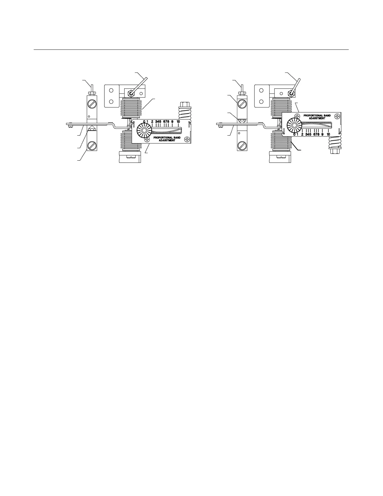
REVERSE ACTING
POSITION
REVERSING BLOCK
(KEY 37)
PROPORTIONAL BAND ASSY
DIRECT ACTING
REVERSE ACTING
GE34724−
A
E1066
RELAY TUBING
(KEY 24)
DIRECT ACTING
POSITION
PROPORTIONAL TUBING
(KEY 25)
PROPORTIONAL BAND
ASSY
DIFFERENTIAL-GAP CONTROLLER
FLAPPER/SCREW
(KEYS 40 AND 46)
REVERSING BLOCK
(KEY 37)
FLAPPER/SCREW
(KEYS 40 AND 46)
PROPORTIONAL TUBING
(KEY 25)
RELAY TUBING
(KEY 24)
BELLOWS
(KEY 52)
BELLOWS
(KEY 52)
Figure 16. Reverse/Direct Acting Tubing Connection for Differential Gap Controller
9. Check to be sure that the beam is parallel with
the bottom of the case and that the link (key 16) is in
tension. If the beam is not parallel with the case,
loosen the machine screws (key 55), reposition the
Bourdon tube to get the beam parallel, and retighten
the screws.
10. If a Bourdon tube with a different range was
installed, remove the machine screw and washer
(keys 61 and 60) and dial (key 6). Install a new dial
having an adjustment range corresponding to the
range of the Bourdon tube. If an optional process
pressure gauge (key 4, figure 21) is being used,
install a new gauge with the appropriate
measurement capability.
11. Check all tubing connections for leaks and the
Bourdon tube machine screws, tighten as
necessary. Perform the appropriate calibration
procedures.
Replacing Bellows Sensing Element
Refer to figure 24 for key number locations unless
otherwise directed.
1. Shut off the supply pressure and process lines to
the controller or transmitter.
2. Disconnect the tubing from the mounting base
(key 57) and calibration adjuster (key 36).
Disconnect the tubing that connects the pressure
block (key 8, figure 21) to the bellows assembly
(key 71), at the pressure block end.
3. Unscrew the four machine screws (key 41,
figure 21 or 22), and remove the pressure sensing
subassembly from the case.
4. Remove the bellows yoke machine screws and
washers (keys 98 and 99), and move the bellows
yoke to the right to permit access to the link screw.
5. Disconnect the link (key 71M) and bearing
(key 71L) from the beam. Be careful to avoid losing
the bearing.
6. Loosen the nuts that secure the bellows
assembly (key 71), and remove this assembly from
the bellows yoke (key 100).
7. For a gauge−pressure sensing element (only one
bellows in the assembly), install the proper bellows
spring (key 104) into the bellows assembly if the
input signal range is being changed.
8. Install the new bellows assembly into the bellows
yoke.
9. Attach the link and bearing to the bellows
assembly. Position the bellows yoke (key 100) on
the mounting base (key 57), and attach the link and
bearing to the beam. Start but do not tighten the four
machine screws (key 98) with washers (key 99) that
attach the yoke to the mounting base. Slide the yoke
up or down as necessary to position the beam
horizontally, as shown in figure 24. Tighten the
machine screws.