EasyManua.ls Logo

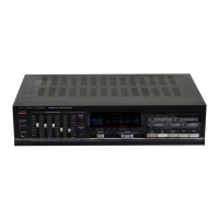
Fisher CA-271 - Parts List; Packing Parts List; Accessories Parts List; Cabinet and Chassis Parts List

Fisher CA-271
19 pages
To Next Page IconTo Next Page
To Previous Page IconTo Previous Page
Loading...
PARTS
LIST
ack
Part
No.
Description
PACKING
PARTS
LIST
3-9415-10300
Bag
Polyethylene
131-6-2119-02090
Bag
Polyethylene-Exp.
131-6-3069-16350
Patching
Sheet
131
-6-9459-00300
Rubber
Band
141-6-1139-86226
Outer
Cor
Carton
(CA-271)
141-6-1139-86230
Outer
Cor
Carton
(CA-1271)
141-6-1469-00400
Pad
Top
141-6-1469-04000
Case
Styrofoam
(Left)
141-6-1469-04001
Case
Styrofoam
(Right)
ACCESSORIES
PARTS
LIST
131-6-2719-10801
Bag
Fan
131-6-4519-15700
Guarantee
Certificate
131-6-4559-11200
Serial
No.
Sheet
142-6-4119-32453
Explanatory
Booklet
(CA-271)
142-6-4119-32501
Explanatory
Booklet
(CA-1271)
CABINET
&
CHASSIS
PARTS
LIST
4-2379-21520
Terminal
Lug
141-6-4559-03300
Serial
No.
Sheet
131-2-7103-26100
Label
131-6-4559-10900
Manufacturing
No.
CAI
131-2-1410-33100
Cover
CAT-1
131-2-3202-13400
Meta!
Reinf
CA2
141-2-4219-38400
Screw,
Bind
Hd.
Tapping-B
Sems
+M4.0x8
CA3
131-2-5205-33300
Cushion
CA4
131-2-1601-69601
Knob
(Speaker
Selector)
CA5
141-2-2149-24300
Panel
Front
CAG
4-6129-70660
Lamp
CA7
131-2-3310-18000
Metal
Mount
Lamp
CA8
131-2-1601-91600
Knob
Power
CAQ
131-2-5205-33500
Cushion
CA10
131-2-1601-91701
Knob
Push
CAI1
141-0-3519-24400
Mount
P.C.B.
Assy
|
141-2-3519-74300
Mount
P.C.E.
141-2-1449-65100
Screen
LED
CA12
131-2-1601-91900
Knob
Volume
CA13
131-2-1601-92000
Knob
Balance
CA14
131-2-3608-16400
Filter
CA15
131-2-4221-00600
Rivet
CA16
131-0-1016-44400
Panel
Decorate
Assy
(CA-271)
CA16
131-0-1016-44402
Panel
Decorate
Assy
(CA-1271)
131-2-1205-28800
Decorate
Plate
Dial
131
-2-1601-91800
Knob
Function
141-2-1129-15200
Cabinet
Front
141-2-1449-61207
Plate
Front
(CA-271)
141-2-1449-61217
Plate
Front
(CA-1271)
141-2-1449-65000
Plate
Decorate
141-2-2899-43500
Adhesive
Film
141-2-2899-43600
Adhesive
Film
CAI7
141-2-1659-35900
Knob
Stide
CA18
141-2-3119-25400
Chassis
CAI
131-0-3016-10400
Cramp
Wire
Assy
CA20
131-2-1801-14100
Leg
CA21
141-2-1259-08100
Plate
Bottom
CA22
131-2-4203-84200
Washer,
4.2x12x1.0Z
CA23
131-2-3101-99900
Metal
Mount
Trans
CA24
ZN
4-2512-23021
Power
Trans
CA25
131-2-4201-25201
Screw,
Brazier
Hd.
Tapping-8.
Seras
+-M3.0x8
CA26
4-2039-71961
Transistor,
2SA
1302
[01
15,
0215,
0505}
or
4-2039-72121
Transistor.
2SA
1301
[Q115,
0215,
0505)
Q’ty
ner
Part
No.
Description
Q'ty
CA27
4-2039-71971
Transistor,
2SC
3281
[0114,
0214,
0506]
3
1
or
4-2039-72111
Transistor,
2SC
3280
[Q114,
0214,
0506]
:
1
CA28
141-2-3129-05800
Sub
Chassis
1
CA29
141-2-3689-14300
Plate
Heat
Sink
1
CA30
131-2-4201-17800
Screw
Ground
1
CA31
141-2-1219-34800
Panel
Rear
(CA-271)
1
CA31
141-2-1219-34802
Panel
Rear
(CA-1271)
1
CA32
131-2-5205-15800
Cushion
1
CA33
141-2-3159-03300
Braket
Cover
j
CA34
131-2-6111-14200
Bushing
(Power
Cord)
CA35
=
A.
4-2432-00200
Power
Cord
CA36
=
A\.4-2312-01020
Switch
Slide
(AC
Selector)
[SW411]
CA37
~—s-_-
A.
4-2359-74032
—2P
Socket
With/Nut
2
1
CA38
131-2-7104-00500
Plate
Pad
Switch
.
1
1
1
P.C.B.
ASSY
PARTS
LIST:2:
1
PCB1
141-0-1939-09162
Main
P.C.B.
Assy
PCB2
141-0-1939-09131
Input
P.C.B.
Assy
PCB3
141-0-1939-09140
Function
P.C.B.
Assy
PCB4
141-0-1939-09150
Graphic
Equalizer
P.C.B.
Assy
PCB5
141-0-1939-09172
Speaker
Terminal
P.C.B.
Assy
PCB6
141-0-1939-09180
Transistor
P.C.B.
Assy
Z
PCB7
141-0-1939-09192
Switch
P.C.B.
Assy
SCREW
PARTS
LIST
Cx
101-3-1302-00311
Screw,
Pan
Hd.
+M2.0x3
CX2
101-3-1303-00611
Screw,
Pan
Hd.
+M3.0x6
=
Cx3
143-3-1302-60611
Screw,
Pan
Hd.
Tapping-B,
+M2.6x6
:
Cx4
143-3-1704-00811
Screw,
Bind
Hd.
Tapping-B,
+M4.0x8
CX5
143-3-1902-60611
Screw,
Brazier
Hd.
Tapping-B,
+M2.6x6
:
CX6
143-3-1903-00611
Screw,
Brazier
Hd.
Tapping-B,
+M3.0xé
£
CX7
143-3-1903-00618
Screw,
Brazier
Hd.
Tapping-B,
+M3.0x6
:
CX8
143-3-1903-00818
Screw,
Brazier
Hd.
Tapping-B,
+M3.0x8
:
CX9
143-3-1903-01011
Screw,
Brazier
Hd.
Tapping-B,
+M3.Cx1>
5
CX10
143-3-1203-00611
Screw,
Flat
Hd.
Tapping-B,
+M3.0x6
2
oX11
101-3-1302-60618
Screw,
Pan
Hd..
+M2.6x6
:
CX12
101-3-1303-00618
Screw,
Pan
Hd.,
+M3.0x6
2
NOTES:
1.
Parts
order
must
contain
Mode!
Number,
Part
Nu~z2°
2-2
Description.
[SO
OC
cop
a
SES
SO
SG
5
GT
0
ee
ne
Ce
ae
eC,
Se
re
OO
ae
Ce
CA
UY
GC
2.
Ordering
quantity
of
screws
and
resistors
must
be
~
10
pcs.
PRODUCT
SAFETY
NOTICE
Each
precaution
in
this
manual
should
be
during
servicing.
Components
identified
with
-
symbol
A\
in
the
parts
list
and
the
schematic
=<
aS
designate
components
in
which
safety
can
be
of
sz=7
=
significance.
When
replacing
a
component
nee
with
A\,
use
only
the
replacement
parts
desig72:+2
parts
with
the
same
ratings
of
resistance.
wa7:
voltage
that
are
designated
in
the
parts
list
in
th
s
~27>
2
Leakage-current
or
resistance
measurements
~_:°
=4
7
Oo
im)
9
insulated
from
the
supply
circuit
before
retus-
-2
°7=
product
to
the
customer.

Related product manuals