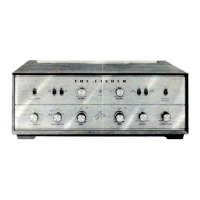
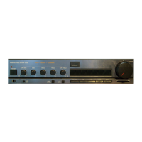
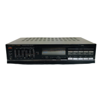
The Fisher X-100 is a stereophonic integrated amplifier, designed to serve as the central control unit for a high-fidelity audio system. It combines preamplification, tone control, and power amplification into a single chassis, offering a comprehensive solution for playing various audio sources through a pair of loudspeakers. The amplifier is engineered to deliver a rich and detailed stereophonic sound experience, characteristic of Fisher's reputation for quality audio equipment during its era.
Function Description
At its core, the X-100 functions as a two-channel audio amplifier, processing separate left and right audio signals to create a stereophonic soundstage. It accepts input from a variety of audio sources, amplifies these signals, and then sends the amplified output to passive loudspeakers.
The amplifier features multiple input options, allowing users to connect different components of their audio system. These inputs typically include:
- Phono Inputs (Magnetic and Ceramic): Dedicated inputs for turntables, accommodating both magnetic cartridge (low-level, requiring RIAA equalization) and ceramic cartridge (higher-level) types. This allows for direct connection and playback of vinyl records, a primary source for high-fidelity listening.
- Tape Head Input: An input specifically designed for direct connection to a tape recorder's playback head, bypassing the recorder's internal preamplifier. This offers a potentially higher quality playback path for reel-to-reel tape decks.
- Tuner Input: An input for connecting an external AM/FM radio tuner, enabling the reception and amplification of broadcast radio signals.
- Auxiliary Inputs (Aux 1, Aux 2): General-purpose inputs for connecting other line-level audio sources, such as CD players (if available at the time), cassette decks, or other external audio devices.
After selecting an input source, the audio signal passes through the preamplifier section. Here, the signal is initially amplified to a usable level and then routed through the tone control circuitry. The tone controls allow users to tailor the frequency response of the audio, adjusting the bass and treble levels to suit their listening preferences or to compensate for room acoustics and speaker characteristics.
Following the preamplifier and tone control stages, the signal enters the power amplifier section. This is where the audio signal is significantly boosted in power to drive loudspeakers. The X-100 is designed to provide sufficient power output for typical home audio environments, ensuring clear and dynamic sound reproduction.
A key feature of the X-100 is its stereophonic capability, meaning it processes and amplifies two independent channels (left and right) of audio. This allows for the faithful reproduction of stereo recordings, creating a sense of space and directionality in the sound. The amplifier also includes a mode selector, which typically allows users to switch between stereo, mono, and possibly reverse stereo or other channel configurations, offering flexibility in how the audio is presented.
Usage Features
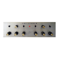
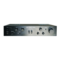
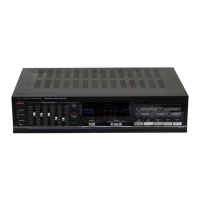
The Fisher X-100 is designed for user-friendly operation, with a front panel that provides intuitive control over its various functions.
- Input Selector: A prominent rotary switch allows users to easily select the desired audio source (Phono, Tape Head, Tuner, Aux 1, Aux 2). This ensures that only the active source's signal is processed.
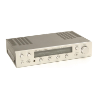
- Master Volume Control: A large rotary knob controls the overall loudness of the audio output for both channels simultaneously. This is the primary control for adjusting listening levels.
- Balance Control: This control allows users to adjust the relative volume between the left and right channels. It's useful for compensating for uneven speaker placement or for personal preference, ensuring the soundstage is centered.
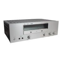
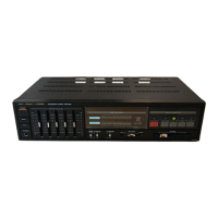
- Bass and Treble Tone Controls: Separate rotary knobs for bass and treble adjustments provide granular control over the low and high frequencies. These allow for fine-tuning the sound to match personal taste, speaker characteristics, or room acoustics.
- Loudness Contour: The "Loudness" switch or control is designed to compensate for the human ear's reduced sensitivity to bass and treble frequencies at low listening levels. When engaged, it typically boosts these frequencies, making the sound fuller and more balanced when the volume is turned down.
- Mode Selector: This switch allows users to choose the desired playback mode, such as "Stereo" for normal stereo listening, "Mono" for combining both channels into a single monophonic signal (useful for older recordings or certain broadcasts), and potentially other modes like "Reverse Stereo" for specific applications.
- Low Level/High Level Switches: These switches might be associated with the phono inputs, allowing selection between magnetic (low level) and ceramic (high level) cartridges, ensuring proper impedance matching and gain for different turntable types.
- Front Panel Indicators: The front panel typically includes an indicator lamp (e.g., a green jewel) to show when the unit is powered on.
- Rear Panel Connections: All input and output connections are located on the rear panel, providing a neat and organized setup. These include RCA jacks for audio inputs, screw terminals for speaker connections, and an AC power cord. Some models might also include switched or unswitched AC outlets for powering other components.
Maintenance Features
While the Fisher X-100 is a robust piece of equipment, like all vintage tube amplifiers, it requires periodic maintenance to ensure optimal performance and longevity. The service manual provides crucial information for technicians and knowledgeable users.
- Tube Layout Diagram: The manual includes a clear diagram showing the location of all vacuum tubes within the chassis. This is essential for identifying and replacing tubes, which are consumable components that degrade over time. The diagram also specifies the tube types (e.g., 12AX7, 7247, 5AR4), making it easy to source replacements.
- Bias Adjust Control: A critical maintenance feature for tube amplifiers is the bias adjustment. The manual details the procedure for setting the bias voltage for the power amplifier tubes. This involves connecting a DC voltmeter to specific test points (e.g., cathode pin #3 of power tubes) and adjusting a potentiometer (Bias Adjust) to achieve a specified voltage (e.g., +44 volts DC). Correct bias setting is vital for optimal sound quality, tube life, and preventing damage to the output tubes.
- Parts Description List: A comprehensive list of all components, including capacitors, resistors, potentiometers, transformers, and miscellaneous parts, is provided. This list includes part numbers, descriptions, and specifications (e.g., capacitance, resistance, tolerance, voltage rating). This information is invaluable for troubleshooting and replacing faulty components, ensuring that original specifications are maintained.
- Schematic Diagram: The detailed schematic diagram is the backbone of any repair or maintenance effort. It illustrates the complete electrical circuit of the amplifier, showing how all components are interconnected. Technicians use this diagram to trace signal paths, identify voltage points, and diagnose problems.
- Fuse Protection: The amplifier incorporates a fuse (e.g., 3.2 amp, slo-blo) to protect the internal circuitry from overcurrent conditions. The manual identifies the fuse type and rating, making replacement straightforward if it blows.
- Transformer Information: Details about the output and power transformers are included, which are critical and often expensive components. This information is useful for diagnosing power supply issues or output stage problems.
- Printed Circuit Board (PCB) Information: If the amplifier uses PCBs (e.g., for equalization, high-frequency filter, tone control), the manual provides part numbers for these assemblies, which can simplify replacement if a board is extensively damaged.
- General Troubleshooting Guidance: Although not explicitly detailed as a "troubleshooting section" in the provided snippets, the comprehensive nature of the manual (schematics, parts lists, tube layout, bias adjustment) implicitly provides all the necessary information for a skilled technician to diagnose and repair common amplifier issues. Regular inspection of tubes for signs of wear, checking for loose connections, and cleaning controls are general maintenance practices that can extend the life of the unit.