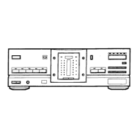
Do you have a question about the Fisher CA-9335 and is the answer not in the manual?
| Power output | 100W per channel (8 ohms, 20Hz-20kHz, 0.1% THD) |
|---|---|
| Total harmonic distortion | 0.1% (20Hz-20kHz, rated power) |
| Input sensitivity | 2.5mV (MM), 150mV (line) |
| Signal to noise ratio | 100dB (IHF-A weighted) |
| Dimensions | 420 x 150 x 360 mm (W x H x D) |
| Weight | 9.5kg |
| Speaker load impedance | 8Ω to 16Ω |
Technical specs for the primary amplifier channel.
Technical specs for the surround amplifier channels.
Technical specs for the center amplifier channel.
Electrical output specifications for various terminals.
Electrical input voltage and frequency specifications.
Physical size (width, height, depth) of the unit.
Physical weight of the amplifier unit.
Specs for the RCA-9335 remote control unit.
Critical safety precautions for component replacement and service.
List of materials included for packaging and accessories.
Comprehensive list of electrical components used in the unit.
List of structural and chassis-related components.
Detailed parts for the main control microprocessor board.
List of screws, fasteners, and hardware for assembly.
List of parts specific to the remote control unit.
Block diagram for the BU4094B IC in the front section.
Block diagrams for LA6458S and LC7536 ICs.
Block diagram for the HA118104 video signal switch IC.
Block diagram for the MC74HC4052N/TC74HC4052AP multiplexer IC.
Block diagrams for LC7821 and LC4966 ICs.
Block diagrams for TC9215P and LA6458DS ICs.
Block diagram for the LA7222 AV switch IC.
Block diagram and pin functions for the PD75108CW-W64 microprocessor.
Block diagram and pin functions for the LA2780 Dolby Pro Logic decoder.
Block diagrams for M50198P and STK401-120 ICs.
Block diagrams for 5V and 12V voltage regulator ICs.
Block diagram for the LA2730 Dolby System IC.
Functional block diagram of the surround decoder system.