Do you have a question about the Fisher MC-715 and is the answer not in the manual?
Detailed list and diagram of turntable components.
Technical parameters for the audio amplifier stage.
Technical parameters for the FM tuner.
Technical parameters for the AM tuner.
Technical parameters for the cassette tape deck.
Technical parameters for the turntable.
General operating specifications and physical dimensions.
Steps for removing the turntable unit from the main cabinet.
Steps for removing the main cabinet.
Accessing and working on the main PCB.
List of packing and protective materials.
List of included accessories.
Detailed list of cabinet and chassis components.
List of electronic components and boards.
Detailed list of mechanism components.
List of screws and E-rings for the mechanism.
Detailed list of turntable components.
Instructions for cleaning the stylus.
Steps for replacing the stylus.
Steps for replacing the cartridge.
Procedure for aligning the AM tuner.
Procedure for FM IF stage alignment.
Procedure for FM RF stage tracking alignment.
Adjusting the detector for minimum distortion.
Adjusting the PLL IC free run frequency.
Procedure for adjusting tape head azimuth.
List of components for the main PCB.
List of various capacitor components.
Lists for semiconductor and resistor components.
Lists for various PCB assemblies.
| Brand | Fisher |
|---|---|
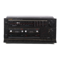
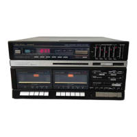
| Model | MC-715 |
| Category | Stereo System |
| Language | English |