21
The outputs of the LFOs each run via a VCA and can therefore be attenuated electroni-
cally. The maximum output voltage is +/- 5V. Using the AMP settings, the output voltage
can be varied over a wide range. It is also possible to control the amplitude using anot-
her LFO.
Press the AMP button once. The button now lights up. After releasing the button, the cur-
rently set value is shown on the display. Change the value using the DATA knob.
Value range: oFF, 001...059, LF1..LF4
oFF the LFO level is zero volts
001..059 level setting between a few mV and max. 5V
LF1..LF4 one of the three remaining LFOs controls the level:
- with LFO-1 only LF2, LF3 and LF4 are displayed
- with LFO-2 only LF1, LF3 and LF4 are displayed
- with LFO-3 only LF1, LF2 and LF4 are displayed
- with LFO-4 only LF1, LF2 and LF3 are displayed
A NOTICE:
If the LFO's VCA is controlled by another LFO, the entire stroke of the LFO wave
affects the amplitude. The AMP setting of the other LFO is ineffective for this control.
However, it still affects the output of the other LFO.
EXAMPLE:
LFO-1 with AMP=LF2 and LFO-2 with AMP=030
The LFO-2 modulates the output level of LFO-1. This directly affects the output jack of
LFO-1 with maximum amplitude of the waveform of LFO-2. The set amplitude of LFO-
2 (value=030) only affects the output socket of LFO-2 and is attenuated by about half.
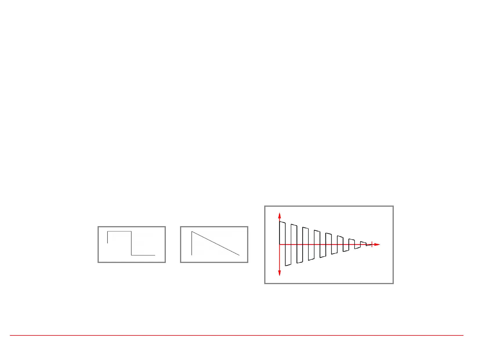
With the help of amplitude modulation by another LFO, slowly decreasing or increa-
sing pulse sequences can be generated, for example!
LFO - AMP (LFO amplitude=output level)
LFO 1
Rectangle,
Rate fast
AMP=LF2 (LFO-2)
+
=
LFO 2
Down linear,
Rate slow
Result at the output of LFO 1:
The output level is through
LFO 2 modulates.
 Loading...