CONNECTION
The device is equipped with the following interfaces:
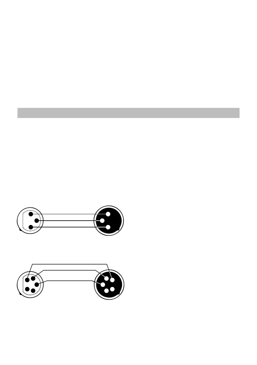
1. DMX (in/out): XLR 3(5)-pin socket
2. Power (in/out): powerCON socket
The connecon is performed using cable with
XLR-female -> XLR-Male plugs.
1
3
2 2
SHIELD
SIGNAL (+)
SIGNAL (-)
3
1
FEMALE
MALE
XLR
1
SIGNAL (+)
SIGNAL (-)
FEMALE
MALE
XLR
2
3
4
5
1
2
3
4
5
CAUTION! At the last xture, the
DMX signal has to be terminated
with a terminator. Solder a 120Ω
resistor between signal (-) and si-
gnal (+) into a XLR plug and plug
it in the DMX output of the last
xture.
3-PIN XLR
5-PIN XLR
5
position and orientation of the
fixture to minimize pooling.
Two quarter-turn brackets are
supplied with the fixtre if it is
to be flown above the ground.
Rig the fixture to a support truss
or structure using the supplied
brackets and suitable clamps.
Fasten a safety cable between
the support structure and the
attachment point on the fixture.
The safety cable must be able to
bear at least 10 times the weight
of the fixture.