'-",;
I
r
C!!N_~A.!?I!!\f~O!!~A~,~O~~M~E.!t"
__
.f--l
L..
__
oJ
,I
'1
(Example: when optional roof air conditioner
is
installed.)
23
NOTE:
Units with automatic switchover power converters
will normally require
uP
to
3 minutes
to
switch
over before current
is
supplied
to
115V outlets.
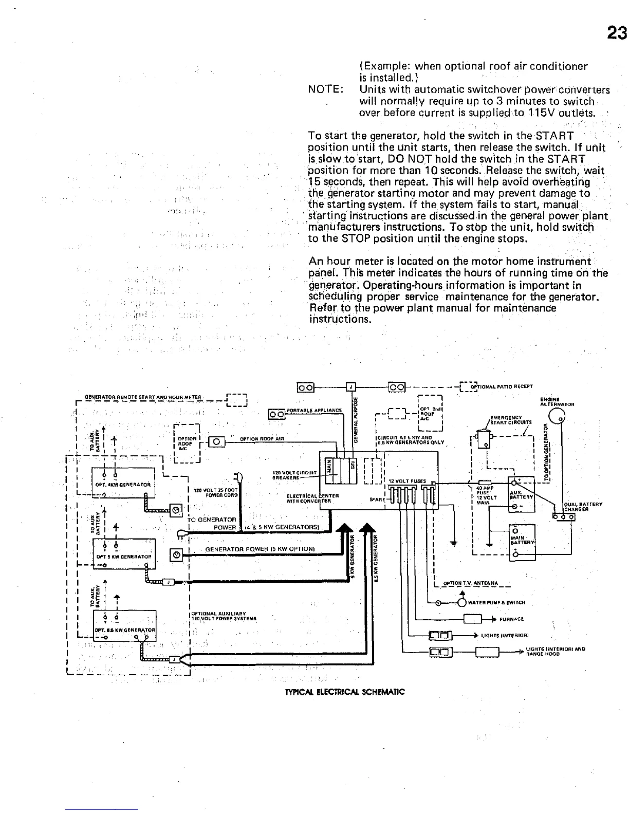
To
start
the
generator, hold
the
switch
in
the
START
position until
the
unit starts, then release
the
switch.
If
unit
isslow
to'start,
DO
NOT hold
the
switch
in
the
START
position for more
than
10
seconds.
Releasethe
switch, wait
15.s,econds, then repeat. This
will
help avoid overheating
th.e.
generator starting
motor
and may prevent damage
to
the
starting system.
If
the
system fails
to
start, manual
.
starting
instructions are discussed in
the
general power plant
'manufacturers instructions.
To
stop
the
unit, hold switch
to
the
STOP position until
the
engine stops.
An
hour
meter
is
located on
the
motor
home
instrument
panel. This meter indicates
the
hours of running time
onthe
generator, Operating-hours information
is
important
in
scheduling proper service maintenance for
the
generator_
Refer
to
the
power
plant
manual
for
maintenance
instructions_ '
o
ol---EI---1<o~oQf--
- - - - -
-[~~~TIONAI.PATIO
REeEPT
o b PORTABLE
APPLIANce
r--l
r-l....
IOP~
2 .... '
r-L.._.J
-:~~F
I
I I I
I L
__
J
EMERGENCY
ENGINE
ALTERNATOR
o
lC"rr:
t
1 "';iw 1 •
I
0::
IT.
jO.~
L I '
r--1
I
OPTION
I 0
,---",,,,,,,n,,o'~'''OO'''''A'''''-,,,,,-
__
-,
I
~~F
r r
I ,
ICIRCUIT
AT
5KW
AND
,6.S
KW
GENERATOAS qNL V _
O
TART CIRCUITS
j
~
r
---
-,
•
I ,
~I
I·t-..,-,
'---·-1
L ___ J
I ' ,
I:
+
~
L
__
I
',I
OPT.'KWGeNERATO~
I 1l0VO\,.T2SFOOT
120
vou
C~"::;'""'''11rrllJ
BREAKERS _
I L
--
--0')
I
POWEn
CORD
I I
'.
I'
I I
)(:::
1
TO
GENERATOR
ELECTRIcAL ENTER
WITH
CONVERTER
,
I
~~
I
I
"
2i
I
.;.
I POWER
14
'&
5 KW GENERATORS)
I
I,
","_
"+1~~G~E~N~ER~A~T~OR~PO~W~E~R~'~5~KW~O~P~TI~O~N'~
__
..
I,
,
..
".
'''''''0'
'"
r .
I--
<--O=-
__
--l!--'
I
~
I
,
•
>i1C
t
:;,~,
+
~,
,
~D-'~----------------------~.
..
: I
,I
,
,
,
I
L_
~:,UKWGENEAA,TOR
','I
I CfTlONAL AUXILIARY
1211,\I0L
T
POWER
SYSH,",S
I'
I"
I
L..:.'..:.
_:
____
:"'~:_...l
I I I
~:
rTL,
. I I I
~I
, I
11
,I
L
___
-,
:
~I
, I
II
. I
0'
LJ
J I
12\10LT
FUSE~''--Q+-_~f'--<;::::l:_-l<I-<:
___
:J
-
,r;;:~:::;;,
'1
!t~:'P
I I
12VOLT
sPARE; 1
MAIN
I
,
,
,
,
,
,
,
I
MAIN
&ATTERY
I
I
,
,
,
,
L
___
_
,
,
L
2".!.!o.!!~
..
~!.'I'~!.N~
__
,--{~--(:J
WATER
PU""~
6.
SWITCH
FURNACE
UGHTS IINTERIOR)
~UAL
BATtERY
CHARIlER
~
LtGHTSUNTERIOR'AND
~-.----~
,.
RANIlEHOOO
TYPICAL
ELECTRICAL
SCHEMATIC
 Loading...