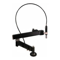
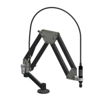
The FlexArm A-32 is a pneumatic tapping and assembly arm designed for industrial applications, offering solutions for tapping and assembly tasks. It is manufactured by FlexArm Inc., a division of Midwest Specialties, Inc.
Function Description:
The FlexArm A-32 is primarily used for tapping and assembly operations, providing a stable and precise platform for air motors. It is designed to facilitate the creation of threaded holes in various materials and to assist in assembly processes where a guided arm is beneficial. The arm utilizes a counterbalance system, typically gas cylinders, to allow the operator to easily maneuver the motor and tool into position with minimal effort. The system includes a filter/lubricator to ensure proper air supply and lubrication for the air motor, which is crucial for its longevity and performance. Quick-change chucks enable rapid tool changes, enhancing operational efficiency. Torque-style tap holders with built-in safety clutches protect taps from breakage, especially in blind or bottom holes, by ratcheting and stopping the tap when it reaches the desired depth or encounters excessive resistance.
Important Technical Specifications:
- Air Supply Requirements: The unit requires an air supply of 90-120 psi and 27-28 cfm at the motor to achieve maximum tap capacity. The incoming airline connection should be 1/4" NPT with a minimum 1/2" I.D.
- Lubrication: Uses ISO Grade 32 hydraulic or spindle oil. Marvel Mystery Oil, synthetic air tool oil, or similar products are not recommended. The lubricator should dispense 1-3 drops of oil per minute.
- Mounting: Designed for secure mounting to a flat, smooth table or workbench using four 3/8" bolts in a specific pattern (4.50" bolt circle, 5.40" outer diameter, 0.406" thru holes).
- Motor RPM and Chuck Style (Examples from A-32 series):
- T4-A32: 400 RPM, Size 1 QC (1/8" in mild steel capacity)
- A32-FX900115: 400 RPM, 3/8" Jacobs (5/16" in mild steel capacity)
- T6-A32: 600 RPM, Size 1 QC (5/16" in mild steel capacity)
- A32-FX900125: 600 RPM, 3/8" Jacobs (3/8" in mild steel capacity)
- T10-A32: 1000 RPM, Size 1 QC (3/8" in mild steel capacity)
- A32-FX900135: 1000 RPM, 3/8" Jacobs (1/2" in mild steel capacity)
- T15-A32: 1500 RPM, Size 1 QC (1/2" in mild steel capacity)
- A32-FX900145: 1500 RPM, 3/8" Jacobs (5/8" in mild steel capacity)
- Cylinder Types (Examples): 40#, 50#, 65#, 72#, 95#, 110#, 120#, 135# long cylinders, prefixed with "C16-".
- Torque Holder Factory Settings (Examples in in/lbs):
- #6 tap: 15
- 1/4" tap: 70
- 3/8" tap: 150
- 1/2" tap: 300
- 5/8" tap: 400
- 1" tap: 1,200
- 2" tap: 7,000
Usage Features:
- Counterbalance Adjustment: The counterbalance can be adjusted by loosening a knob on the weight block and sliding it along the arm. Moving the block towards the motor decreases counterbalance, while moving it away increases it. This allows operators to set the arm to their preference and helps extend cylinder life by keeping the motor in an upward position when not in use.
- Quick-Change Chuck System: Facilitates fast and easy tap holder changes. Tap holders are inserted by depressing a locking ring or pushing up a collar, aligning ears with drive slots, and then releasing to lock.
- Torque-Style Tap Holders: Essential for blind or bottom holes, these holders feature a safety clutch that ratchets and stops the tap when it reaches the bottom of the hole, preventing over-torqueing and tap breakage.
- Adjustable Torque Holder Clutch Setting: Factory preset for mild steel, the torque setting can be adjusted for harder materials (increased torque) or softer materials/plastics (decreased torque) to prevent tap breakage or over-torqueing. Adjustment involves removing a snap ring, turning an adjustable thread ring with a spanner wrench, and reinserting the snap ring. Adjustments should be made in small increments (no more than one notch at a time).
- Operating Procedure: Involves securing the workpiece, selecting the correct tap holder and tap, positioning the tap over the hole, actuating the motor with a throttle lever, and gently guiding the tap. For through holes, ensuring sufficient clearance below the workpiece is important. Reversing the motor's rotation to remove the tap is done by actuating the throttle lever and reverse button simultaneously.
- Safety Guidelines: Emphasizes reading the manual, wearing eye protection, avoiding jewelry and gloves, tying back hair, turning off air supply before maintenance or adding oil, keeping hands clear of moving parts, and not altering the machine. Crucially, the mounting surface must be lagged to the floor and secure to prevent serious injury or damage.
Maintenance Features:
- Oiling the Motor: Periodically check the lubricator's flow rate (1-3 drops/minute). If the arm has been idle, 4-5 drops of oil can be added directly to the motor inlet to prime the vanes.
- Cleaning the FlexArm: Regular cleaning with an airline to remove dirt, debris, and chips is recommended. Avoid using oil, WD-40, or other lubricants on arm joints (they are self-lubricating). Do not use harsh cleaners or solvents.
- Base Mount Maintenance: If the unit is removed from the base, prevent contamination of the shaft and needle bearings. If contaminated, thoroughly clean and re-grease with NLGI #2 grade GC-LB lithium complex EP grease.
- Bolt Tightness Check: Periodically inspect and tighten all bolts. Use Loctite 242 (blue) on threads if bolts loosen.
- Filter/Lubricator Maintenance: Ensure the lubricator dispenses 1-3 drops/minute of 10 wt. hydraulic or light spindle oil (EP-32 recommended). Regularly clean the filter and drain excess water from the filter bowl.
- Quick-Change Chuck Maintenance: Keep the motor and chuck free from contamination. Use an airline to blow away dust and dirt. For excessive buildup, soaking the chuck in cleaning solvent or WD-40 may be necessary. Disassembly procedures are provided for both knurled and smooth collar chucks, with warnings about losing ball bearings or springs.
- Cylinder Replacement: Gas cylinders are wear items. If counterbalance is lost, cylinders need replacement. The cylinder part number (C-16_____) is printed on the cylinder barrel. Replacement cylinders have a 30-day warranty, void if the shaft or body shows scratches/nicks. Detailed steps for removal and installation are provided, including supporting the arm, removing motor mount screws, arm guard, and carefully handling the cylinder and arm pins. Re-adjustment of counterbalance is required after cylinder replacement.