Document Title Document No. Revision
Date Section
Supplement S3 to the AMM CTLS-LSA –
CTLS-LSA with ROTAX 912iS
AF 0480 0011 00 05-Aug-12 28-00-3
Approval Ref.: Approved on the Basis of Manufacturer Self Declaration
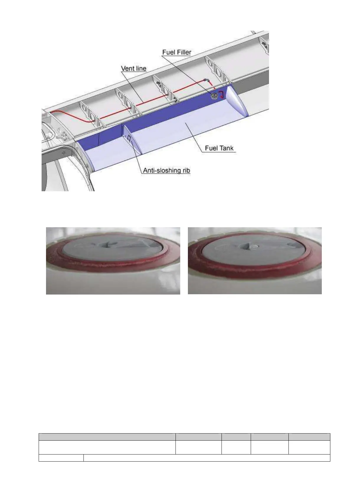
Fig. 28-00-2
To open the fuel filler cap, the lever in the cap must be raised and turned 90° anti-
clockwise. The cap can then be removed. The cap is properly shut when the lever is
pressed down into position (Fig. 28-00-3).
Incorrect position Correct position
Fig. 28-00-3
Fuel flows via a flapper valve into the inner section of the fuel tank inboard of the anti-
sloshing rib. The flapper does not completely seal the inner tank. But it does greatly restrict
the return flow of fuel into the outer chamber when one wing is low (sideslip).
A special epoxy covering is applied to the inner surface of the fuel tank. The covering is
resistant to fuel and ethanol and ensures continued leak resistance of the tank.
The outlet with integrated coarse screen is installed in the wing root rib. The outlet can be
removed via a maintenance plate in the root rib for visual inspection and cleaning. The
maintenance plate is provided with a sight gauge. When wings attached to the fuselage
the sight gauges are visible to the occupants (Fig. 28-00-4).
 Loading...