Document Title Document No. Revision
Date Section
Supplement S3 to the AMM CTLS-LSA –
CTLS-LSA with ROTAX 912iS
AF 0480 0011 00 05-Aug-12 28-00-4
Approval Ref.: Approved on the Basis of Manufacturer Self Declaration
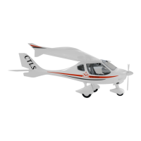
Fig. 28-00-4
The tanks are vented via tubes in the outer tank sections, the air coming from NACA inlets
on the outer side of each of the upper winglets. The vent tube is led through the outer tank
section in a loop. In this way, no fuel can escape into the vent tubes should the aircraft be
parked at a slant.
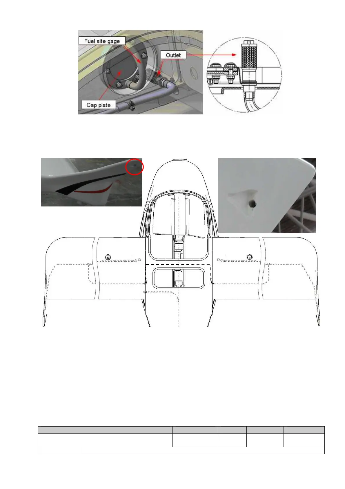
Fig. 28-00-5
The header tank has venting line routed to the left wing tank. The vent tube is led through
the tank along the upper wing skin to the highest point of fuel tank. Due to this, overflow
fuel from the header tank goes to the left wing tank and cannot be spilled (Fig. 28-00-5).