Document Title Document No. Revision
Date Section
Supplement S3 to the AMM CTLS-LSA –
CTLS-LSA with ROTAX 912iS
AF 0480 0011 00 05-Aug-12 28-00-6
Approval Ref.: Approved on the Basis of Manufacturer Self Declaration
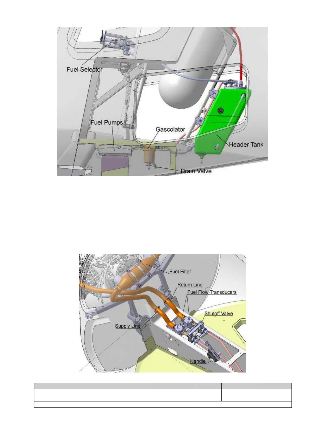
Fig. 28-00-8
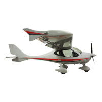
The fuel shutoff valve is located after Fuel pumps, on the tunnel. This valve closes both,
feed line and back flow line and therefore completely separates the engine compartment.
As an option two fuel flow transducers can be placed after the shutoff valve. Fuel
consumption metering is achieved by the difference between the feed line and the back
flow line fuel flow. If fuel the flow transducers are not set, the fuel consumption is
calculated by the engine control unit (ECU).
From the shutoff valve fuel flows through the very fine fuel filter to the injection lines, fuel
pressure sensor, the injection valves and the fuel pressure regulator. The fuel pressure
regulator feeds any surplus fuel back to the header tank (Fig. 28-00-8).
Fig. 28-00-9