Document Title Document No. Revision
Date Section
Supplement S3 to the AMM CTLS-LSA –
CTLS-LSA with ROTAX 912iS
AF 0480 0011 00 05-Aug-12 79-00-2
Approval Ref.: Approved on the Basis of Manufacturer Self Declaration
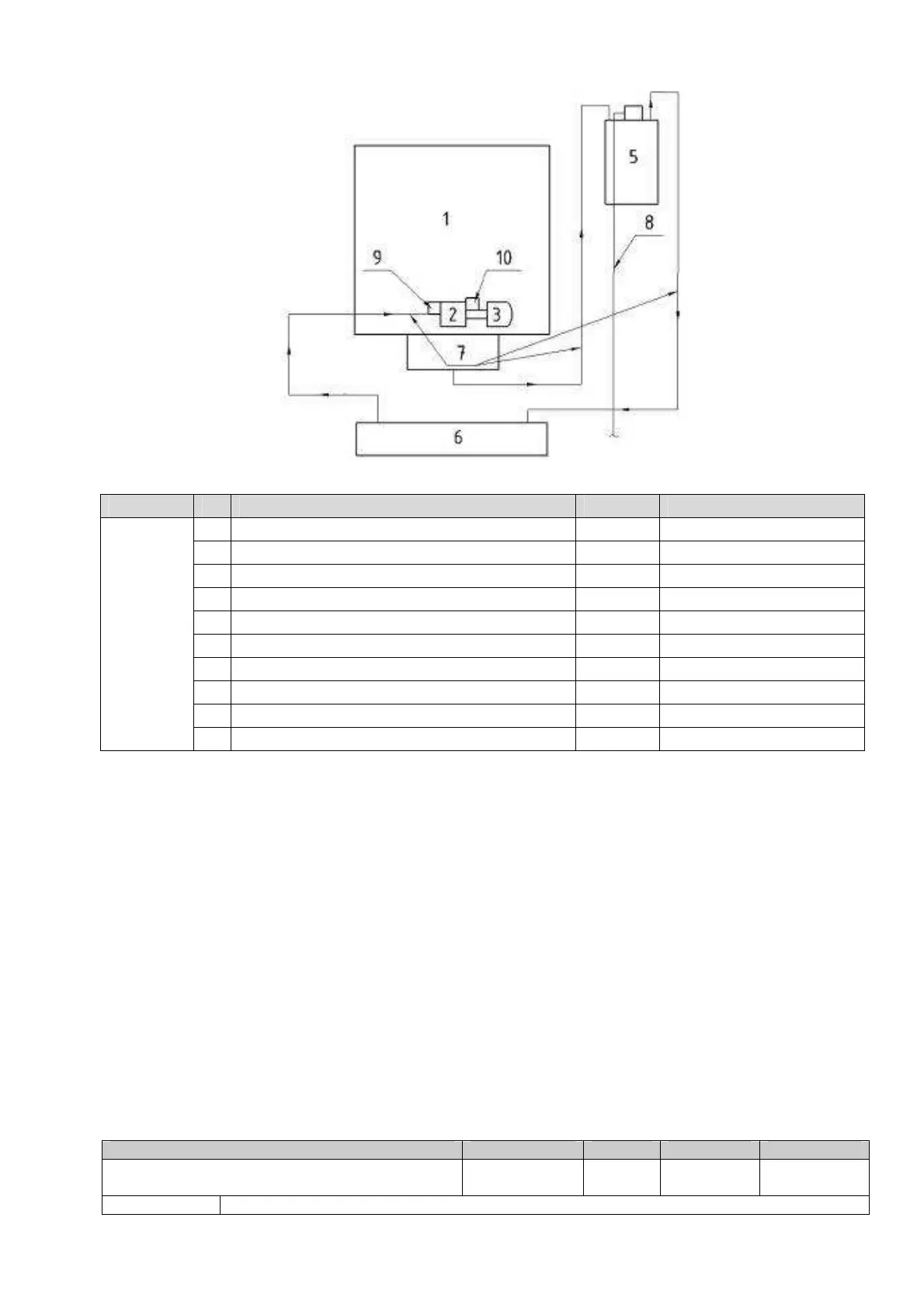
Fig. 79-00-2. Oil System diagram
Fig. Item
Part Name Torque Reference
1 Engine ROTAX® 912 iS C9997789Z/C9997791Y
2 Oil pump C9993515J
3 Oil filter C9997793R
4 Oil thermostat C9997793Y
5 Oil tank C9997791I
6 Radiators Unit KF79000050
7 Oil hose C9997792D
8 Fuel hose (vent line) C9993184G
9 Oil pressure sensor C9997798O
79-00-1
79-00-2
10 Sensor for oil temperature C9997793X
When in operation, the oil pump draws the oil from the oil tank through the thermostat to
the oil radiator and forces it through the oil filter to the lubrication points. From here the
engine oil is distributed to all lubrication points and flows from there back into the oil tank,
driven by piston blow-by gases.
When installed, the thermostat bypasses the radiator when the oil temperature are below
the normal operating temperature range.
In case of the oil filter mat clogging, an emergency pressure valve will open and unfiltered
lube oil will flow to lubrication points.
 Loading...