Star Washer
Hex Nut (2)
Amber LED
Indicator Light
Red LED
Indicator
Light
START
Pushbutton
Switch
RECORD/PLAY
Toggle Switch
DCR
TM
Control
Panel
#6-32 Non-Magnetic
Screw (2)
LED
Holder (2)
RECORD
PLAY
START
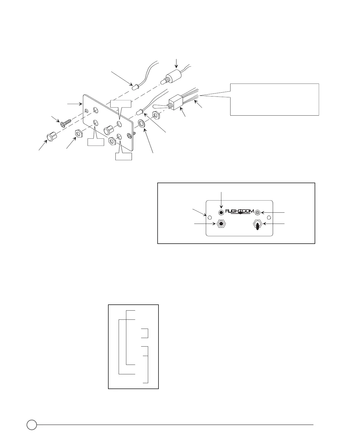
Position toggle switch body so that
the RED WIRES are at the bottom
closest to the word PLAY on the front
side of the panel (Applies to both
vertical and horizontal orientation).
Insert LED Holders into panel
holes BEFORE installing LEDs.
RED
Wires
1.
3.
2.
Assemble the DCR
TM
Control Panel
before mounting either vertically
or horizontally.
Figure 12 - DCR
™
Control Pane
PLAY
RECORD
START
Amber LED
Red LED
Toggle SwitchPushbutton
1/8" Dia.
Mounting Hole (2)
Digital
Clearance
Recorder
®
Figure 11 - DCR™ Control Panel-Exploded View
Figure 12 - DCR™ Control Pane
Figure 13 - By-Pass Plug Wiring Diagram
1
2
7
8
9
11
13
17
21
DB25-f
If you need to remove
your intercom for service,
follow this wiring diagram
for a by-pass plug, so that
radio audio may still be
heard even when the
intercom is removed.