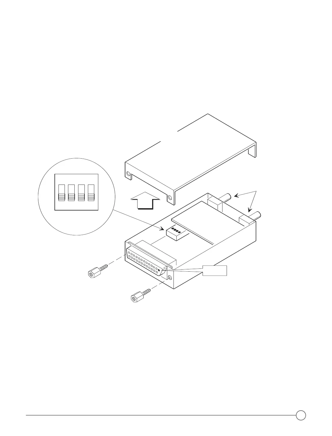
Case Top Removal
To open the Model 403 or 403d intercom case:
1. Remove the two hex screws at the rear of the intercom on either side of the 25-pin D-sub connector (DO NOT
remove the screw on the side of the case). (Figure 10 below)
2. Loosen, but do not remove the two bushing nuts on the Volume and Squelch controls.
3. Carefully pry the top of the case upward, starting from the rear of the case at the 25-pin D-sub connector.
The front of the top of the case fits snugly behind the panel end where the shafts protrude, and will require
gentle but firm removal.
4. Carefully re-attach the top of the case.
5. Tighten the two bushing nuts.
6. Replace the two hex screws.
DCR™ Control Panel Installation
To install the DCR™ control panel:
1. Find a location for mounting the DCR™ control panel that is readily accessible for the pilot or radio operator.
2. Using the DCR™ control panel as a template to locate the six mounting holes, drill appropriate sized holes in
the panel. The DCR™ control panel may be mounted either vertically or horizontally (page 10, Figure 11 and
Figure 12).
3. Permanently secure the amber and red LEDs to the Control Panel with a small amount of strong glue on the
back of each LED and LED holder.
By-Pass Plug Wiring
If you need to remove your intercom for service, install a by-pass plug, so that radio audio may be heard without
the intercom (page 10, Figure 13).
Figure 10 - Case Top Removal & DIP Switch Access
9