3 Insert the intercom through the aircraft panel and the small intercom control panel with the correct side facing
outward.
4. Attach the intercom and control panel to the aircraft panel using two 4-40 by 1/2 inch mounting screws.
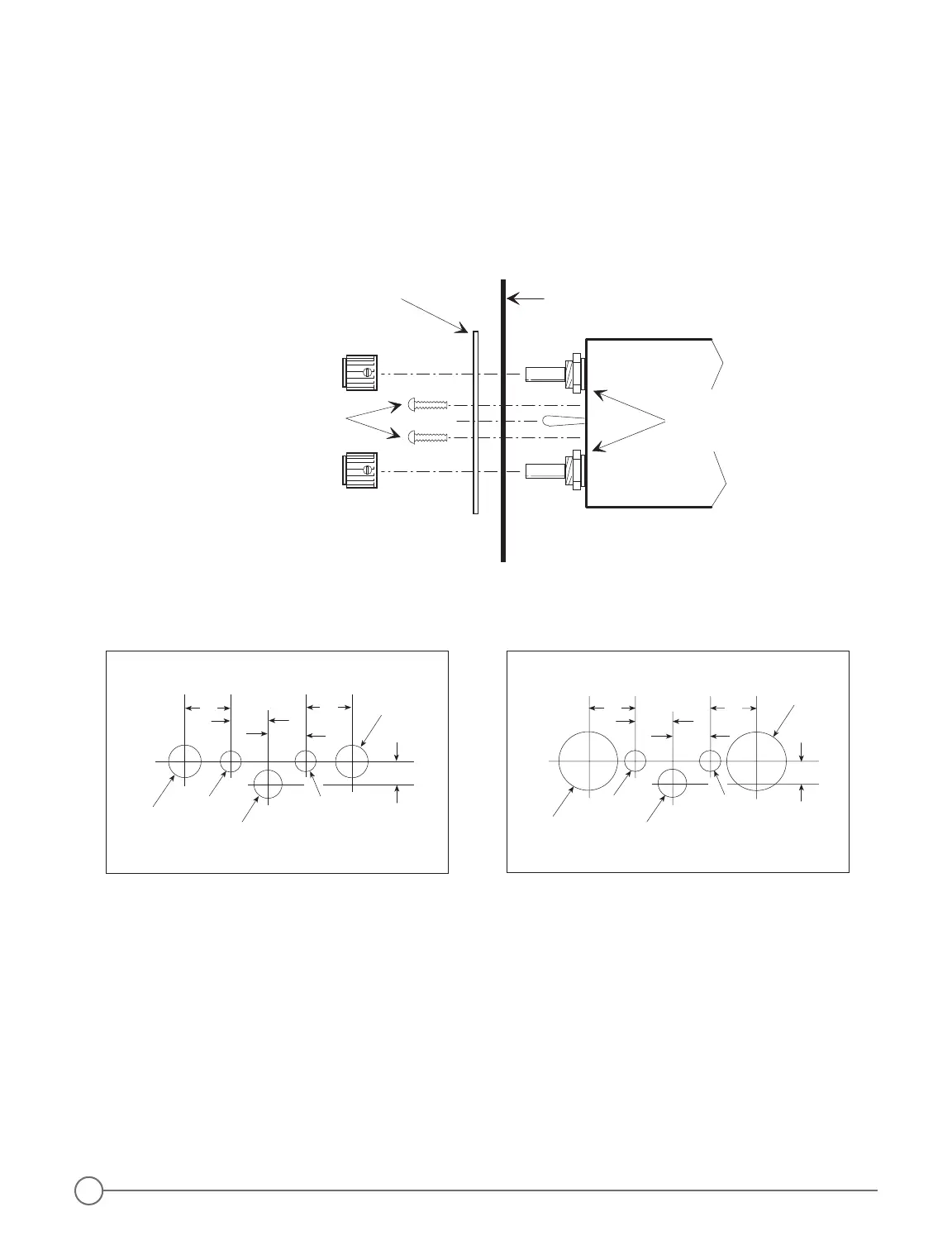
5. Attach the Volume and Squelch control knobs so that they both point to the 7 o’clock position when they are
rotated completely counter-clockwise.
CAUTION: to avoid contact with parts inside the intercom, do not use screws longer than 1/2 inch.
Figure 4 - Drill Templates
Figure 3 - Small Intercom Faceplate Installation
Headphone and Microphone Jack Installation
The 403 and 403d intercoms can be installed as either a stereo/monaural, monaural only, or stereo only system.
With either type of installation you may leave the existing aircraft headphone and microphone jacks in place to
use as a convenient tie in point at which to connect wires 8, 17, and 21 to the radio, or you may connect the
intercom to an audio panel instead of the aircraft jacks. You can also use the existing jacks as a standby radio
connection if you remove the intercom for servicing.
With all three types of installation, you must insulate the microphone jacks from the airframe, but you may either
ground the headphone jacks to the airframe or insulate them with a separate ground wire running back to the
intercom.
NOTE: do not use the same ground wire for headphone and microphone jacks, even when the ground wires
are connected at the same location on the intercom.
2