EasyManua.ls Logo

FLIR MPX - User Manual

FLIR MPX
2 pages
Print Icon
To Next Page IconTo Next Page
Loading...
Language
Video Format
Backlight
OFF
WDR
BLC
HLC
DNR
Advanced Lens ELC
ALC
Exposure
Brightness
Shutter
Sens-Up
AGC
White Balance
Auto
ATW
Preset
Manual
Day&Night
Mode
Delay
D N Level
N D Level
Smart IR
Smart IR Level
Image
Sharpness
Color Gain
Freeze
Flip
D-Zoom
Defog
Special Black Level
Privacy
DP Comp
Reset
Version
Exit
To use the OSD menu:
OPTIONAL: Connect a test monitor to the
camera’s analog (yellow) BNC connector.
Push the middle of the joystick to open the
OSD menu.
Move the joystick / to select a setting,
then / to change the setting value.
Push the middle of the joystick to confirm selection.
Arrows beside settings indicate a submenu ( ).
Select the setting and push the joystick to enter.
Select RETURN and push the joystick to return to the
previous menu, or EXIT from the main menu to exit.
Configure OSD menu options using the
integrated control stick on the camera
cable (see image to the right).
See the full OSD menu tree below. For detailed
explanation of camera settings, see the OSD
instruction manual on www.flirsecurity.com/pro.
Package Contents
MODEL: C233EC/
C233ECP
QUICK START GUIDE
English Version 2.0
www.flirsecurity.com/pro
FLIR Systems, Inc., Copyright © 2015
As our products are subject to continuous improvement, FLIR
Systems Inc. reserves the right to modify product design,
specifications and prices, without notice and without incurring
any obligation. E&OE
Safety Precautions
Use an appropriate low voltage power cable to
prevent fire or electrical shock.
Make sure to install the camera in an area that can
support the camera weight.
There are no user serviceable parts inside the
camera. Please do not disassemble the camera.
Do not clean the lens cover with an abrasive cleaning
material. Please use a soft cloth to clean the lens
cover.
1.3MP Fixed WDR Dome Camera
www.flirsecurity.com/pro
VISIT
1x 1.3MP Fixed WDR Dome Camera
4x Mounting Screws
4x Drywall Anchors
1x Allen Key
1x Power Pigtail Adapter
1x Mounting Template
NOTE: 12V DC adapter not included.
On-Screen Display (OSD) Menu
IT’S ALL ON THE WEB!
Question and Answer IconNeed help?

Do you have a question about the FLIR MPX and is the answer not in the manual?

Summary

On-Screen Display (OSD) Menu

OSD Menu Operation

Instructions for navigating and using the On-Screen Display menu controls.

Installing the Camera

Camera Installation Steps

Step-by-step guide for physically mounting and connecting the camera.

Setting up the Camera

Camera Wiring and Connections

Details on connecting the camera's video and power cables for operation.

Extension Cable Options

Guidelines on maximum lengths for various types of extension cables.

Camera Specifications

Overview

This document describes the FLIR MPX 1.3MP Fixed WDR Dome Camera, providing instructions for its installation, setup, and configuration. It also outlines safety precautions and package contents.

Function Description

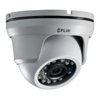
The FLIR MPX 1.3MP Fixed WDR Dome Camera is a surveillance device designed for monitoring and recording video. It features Wide Dynamic Range (WDR) technology, which helps capture clear images in scenes with both very bright and very dark areas. The camera supports both digital 720p MPX HD-CVI output for high-definition recording with compatible MPX DVRs and analog composite 1.0Vpp output for use with analog DVRs, providing flexibility in system integration. Its dome design is suitable for various indoor and outdoor environments, offering an IP66 environmental rating for protection against dust and water. The camera is equipped with IR LEDs to provide night vision capabilities, ensuring surveillance even in low-light or no-light conditions.

Usage Features

On-Screen Display (OSD) Menu Configuration: The camera features an integrated control stick on its cable for easy configuration of OSD menu options. To access the OSD menu, push the middle of the joystick. Navigation is intuitive: move the joystick up or down to select a setting, then left or right to change its value. Pushing the middle of the joystick confirms a selection. Submenus are indicated by arrows next to settings; selecting these and pushing the joystick enters the submenu. To exit a menu, select "RETURN" to go back to the previous menu or "EXIT" to leave the main menu. For detailed explanations of camera settings, users are directed to the OSD instruction manual available on the manufacturer's website.

Key OSD Menu Options: The OSD menu allows for extensive customization of the camera's performance.

  • Language: Sets the display language for the OSD.
  • Video Format: Configures the video output format.
  • Backlight: Offers options like OFF, WDR (Wide Dynamic Range), BLC (Backlight Compensation), and HLC (Highlight Compensation) to optimize image quality in challenging lighting conditions.
  • DNR (Digital Noise Reduction): Reduces image noise for clearer video, especially in low light.
  • Advanced Settings:
    • Lens: Allows selection between ELC (Electronic Light Control) and ALC (Automatic Light Control) for lens control.
    • Exposure: Adjusts Brightness, Shutter speed, Sens-Up (sense-up), and AGC (Automatic Gain Control) to control the amount of light reaching the sensor.
    • White Balance: Provides options such as Auto, ATW (Auto Tracking White Balance), Preset, and Manual to ensure accurate color reproduction under different lighting.
    • Day&Night: Configures the camera's behavior for day and night operation, including Mode, Delay, DN Level, ND Level, Smart IR, and Smart IR Level.
    • Image: Offers adjustments for Sharpness, Color Gain, Freeze, Flip, D-Zoom (digital zoom), Defog, Black Level, Privacy (privacy masking), and DP Comp (defect pixel compensation).
  • Special: Contains additional specialized settings.
  • Reset: Resets all camera settings to their factory defaults.
  • Version: Displays the camera's firmware version.
  • Exit: Exits the OSD menu.

Installation Process: The installation process is designed to be straightforward, starting with a crucial pre-installation step:

  1. Pre-Installation Test: Before permanent mounting, it is recommended to temporarily connect the camera(s) and cables to the DVR to test functionality.
  2. Disassembly: Use the included Allen key to loosen the security screw on the dome cover. Rotate the camera base counter-clockwise to separate it from the ball camera and dome cover.
  3. Mounting: Use the provided mounting template to mark and drill holes. Insert drywall anchors if mounting into drywall. Feed the camera cable through the camera base.
  4. Wiring: Connect the video and power cables as detailed in the "Setting up the Camera" section.
  5. Secure Base: Attach the camera base to the mounting surface using the included screws.
  6. Reassembly and Positioning: Position the dome cover over the ball camera and twist clockwise onto the camera base, but do not tighten completely yet. Move the ball camera to the desired position. While holding the ball camera in place, twist the dome cover the rest of the way to secure it to the camera base. This prevents the camera from moving while tightening.
  7. Final Tightening: Use the included Allen key to tighten the security screw on the dome cover, securing the camera in place.

Camera Wiring and Connectivity: The camera offers dual connectivity options:

  • MPX Connection: Connect one of the two BNC connectors on the camera to an MPX DVR for 720p viewing and recording.
  • Analog Connection: Connect the other BNC connector to an analog DVR for 960H viewing and recording.
  • Power Connection: Connect the included power pigtail to the camera, then connect its terminating wires directly to a DC power source. Alternatively, a 12V DC power adapter (not included) can be connected to the camera and a local power outlet. Users are advised to check polarity specifications for pigtail connections and to use a regulated 12V DC power supply to prevent damage and void the warranty. The power connection length should not exceed 200ft (61m) to avoid affecting camera focus.

Extension Cable Options: The entire length of the cable run between the camera and the DVR should use a single extension cable. Recommended cable types and their maximum lengths are:

  • RG59 20AWG Conductor 95% Braid (CSA/UL or C(UL) Approved): Up to 1500ft (455m).
  • RG6 20AWG Conductor 95% Braid (CSA/UL or C(UL) Approved): Up to 2300ft (700m).
  • Analog CCTV Balun: Up to 300ft (91m). Long cable runs over 1000ft (300m) may be affected by electro-mechanical interference (EMI), which can increase noise in the picture.

Maintenance Features

Safety Precautions: Adhering to safety precautions is essential for the longevity and proper functioning of the camera, as well as user safety:

  • Power Supply: Always use an appropriate low voltage power cable to prevent fire or electrical shock. A regulated 12V DC power supply is required; using a non-regulated or non-conforming power supply can damage the product and void the warranty.
  • Mounting Location: Ensure the camera is installed in an area that can adequately support its weight.
  • Internal Components: The camera contains no user-serviceable parts. Users should not attempt to disassemble the camera.
  • Cleaning: Do not use abrasive cleaning materials on the lens cover. Instead, use a soft cloth to clean the lens cover to prevent scratches or damage to the optical components.

Product Improvement and Updates: FLIR Systems, Inc. reserves the right to modify product design, specifications, and prices without notice, reflecting a commitment to continuous improvement. This means that while the core functionality remains consistent, minor enhancements or changes may be introduced over time. Users are encouraged to check the manufacturer's website for the latest documentation and support resources.

FLIR MPX Specifications

General IconGeneral
Frame Rate9 Hz
Sensor TypeMicrobolometer
Lens OptionsFixed
Resolution80 x 60 pixels
DisplayNo
Video OutputNo
StorageNo

Related product manuals