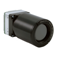
Do you have a question about the FLIR Tau Camera TAU-0035-00-10 and is the answer not in the manual?
| Sensor Type | Uncooled VOx Microbolometer |
|---|---|
| Resolution | 336 x 256 |
| Spectral Range | 7.5 - 13.5 µm |
| NETD | <50 mK |
| Frame Rate | 30 Hz |
| Operating Temperature | -40°C to +80°C |
| Output Interface | Analog video |
| Dimensions | 44.5 x 44.5 x 30.0 mm (without lens) |
Details different lens options, resolutions, and fields of view for the Tau camera.
Lists key performance metrics, operating parameters, and features of the Tau camera.
Provides instructions and precautions for safely unpacking the camera from its packaging.
Describes the VPC module for USB connectivity, power, and communication.
Details the Camera Link module for digital video output and high-speed data transfer.
Explains the locking ring and tool for mounting WFOV cameras into bulkheads.
Describes the accessory for mounting the Tau camera onto a standard tripod plate.
Details the board that adapts the Tau camera to Photon camera connectors.
Covers the kit including the Replicator Board for Photon compatibility.
Explains software for supplementary calibration with customer-furnished lenses.
Provides information on the SDK for camera control via programming languages.
Explains connecting and operating the camera via USB using VPC or Camera Link modules.
Details remote control via RS-232 or the FLIR Camera Controller GUI.
Step-by-step guide for installing the FLIR Camera Controller GUI software.
Instructions for establishing a USB connection between the Tau camera and a PC.
Provides common issues and solutions for the FLIR Camera Controller GUI.
Describes how to use the FLIR Camera Controller GUI interface and view status.
Explains the settings available in the Setup tab of the GUI for camera configuration.
Details options for modifying analog video output settings like orientation and standard.
Explains how to configure digital video output modes (LVDS, BT.656, CMOS).
Describes how to capture and save images using the GUI's Image Capture tab.
Covers Automatic Gain Control (AGC) modes and parameter adjustments for image optimization.
Explains how to set a Region of Interest (ROI) for AGC algorithm calculations.
Details thermal measurement capabilities like Spot Meter and Isotherm modes.
Describes the BT.656 digital interface, its pinout, and timing.
Details the CMOS digital interface, its pinout, and timing characteristics.
Explains the discrete input/output pins and their functions for controlling the camera.
Covers the legacy LVDS digital data channel for compatibility with Photon accessories.
Provides technical details on the legacy LVDS digital data channels and timing.
Details the camera's DC power requirements, voltage range, and consumption.
Describes the main 50-pin Hirose connector interface and its mating parts.
Explains the analog video output capabilities, standards (NTSC/PAL), and characteristics.
Details the RS-232 serial interface for remote camera command and control.
Covers the LVDS digital data channel for real-time serialized digital video output.
Explains the parallel digital data channel configured for CMOS or BT.656 format.
Lists pin definitions for the I/O Module's power, video, serial, and digital data connectors.
Details the asynchronous serial interface for camera control via RX, TX, and GND signals.
Explains the serial port settings, packet protocol, and message structure for camera communication.
Defines the status byte values used by the camera to indicate command receipt and execution.
Lists valid commands that can be set in the Function Byte for camera control.
Provides an example of setting and getting FFC mode via a serial message.
Describes various serial commands for camera settings, AGC, pan/tilt, DDE, and more.
Guides on powering the camera and obtaining video using the Photon Accessory Kit.
Explains remote control via RS-232 using the development kit or FLIR GUI.
Details connecting the serial communications interface using a PC serial cable.
Provides mechanical interface control document for WFOV cameras.
Details mechanical interface for 5mm to 19mm lens core configurations.
Provides mechanical interface description for 25mm lens core configurations.
Details mechanical interface description for 35mm lens core configurations.
Covers mechanical interface description for 60mm lens core configurations.
 Loading...